Pipe-in-Pipe in RCC for Subsea Transfer of Cryogenic Fluids

Inactive Publication Date: 2010-11-18
LIU XUEJIE
View PDF19 Cites 16 Cited by
  • Summary
  • Abstract
  • Description
  • Claims
  • Application Information

AI Technical Summary

Benefits of technology

[0030]It is another object of the invention to provide a method so that therma

Problems solved by technology

They are easily accessed by crew, but are very costly and require maintenance.
In addition, the tunnel creates a dry environment under water.
Building those big tunnels is costly and time-consuming.
These systems have the same shortcomings: not retrievable and subjected to damage by external forces such as shipping anchors and sinking ships.
If

Method used


Image

  • Pipe-in-Pipe in RCC for Subsea Transfer of Cryogenic Fluids
  • Pipe-in-Pipe in RCC for Subsea Transfer of Cryogenic Fluids
  • Pipe-in-Pipe in RCC for Subsea Transfer of Cryogenic Fluids

Examples


Example

[0039]1. System

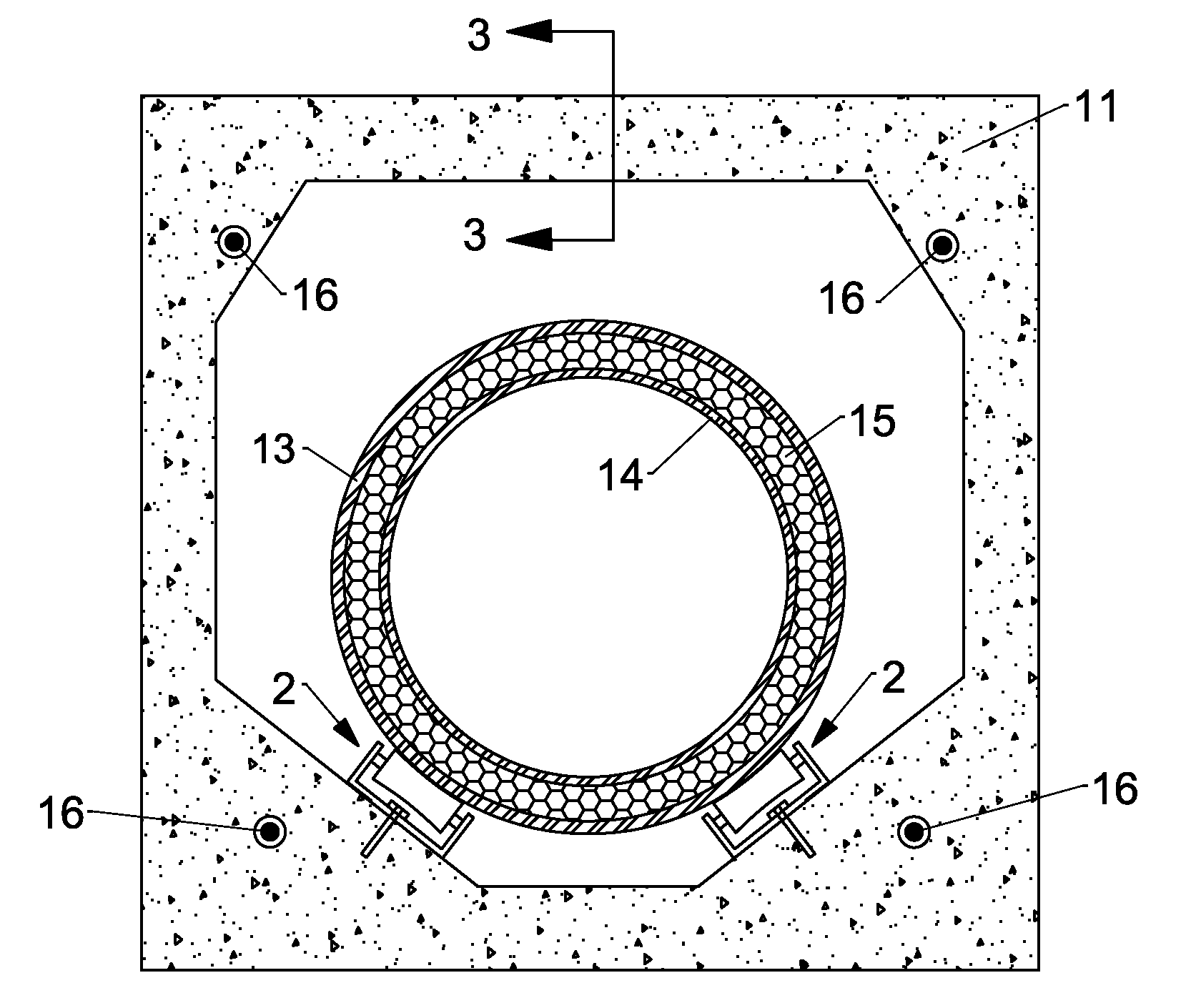
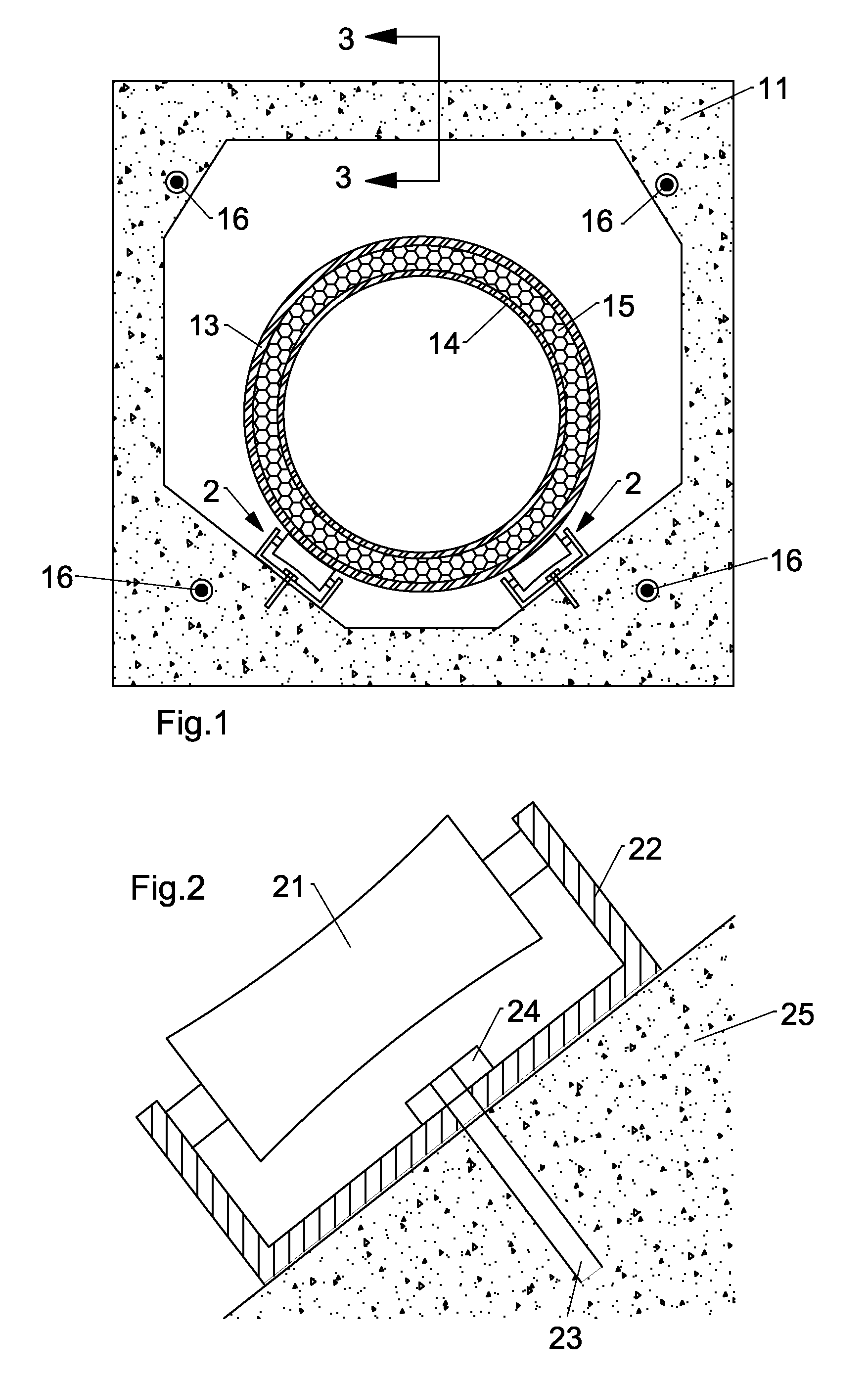
[0040]A simple subsea transfer system of the present invention is illustrated in FIG. 1. The system comprises a reinforced concrete conduit (RCC) 11, double rollers 2 that sit on the bottom of RCC, and a metal casing pipe 13 supported on double rollers 2. Within metal casing pipe 13, there is an inner metal pipe 14 with insulation 15 filled in the annulus in between. Tensioner 16 is located at each corner of RCC 11 and puts in RCC 11 in compression.

[0041]Refer now to FIG. 2, a roller 21 is attached to both walls of a U-shaped support 22. The bottom of U-shaped support 22 is anchored to concrete bottom 25 by tightening nut 24 onto a pre-imbedded stud 23.

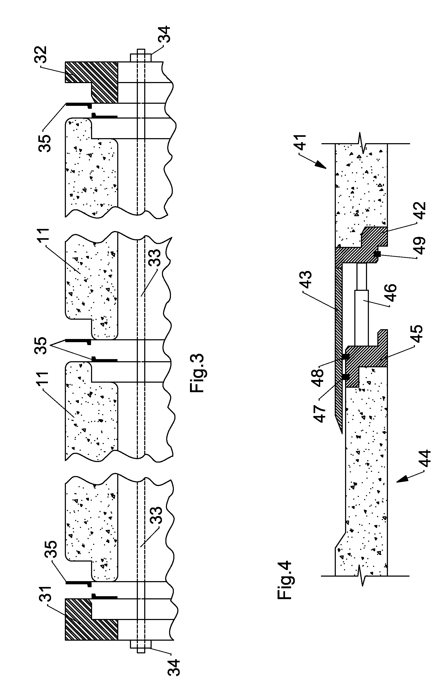
[0042]FIG. 3 shows two reinforced concrete conduits 11, each having a spigot end and socket end. Threaded bar 33 runs through reinforced concrete conduits 11 and is anchored to socket end plate 31 and spigot end plate 32. Rubber gasket ring 35 is used at each joint and provides sealing against water or debris intrusion....


PUM


Abstract

The present invention provides a subsea transfer system for cryogenic fluids comprising reinforced concrete conduits (RCC), and stationary rollers that are anchored to the bottom of RCC, and one or more pipe-in-pipe that is supported on rollers along with insulation in the annulus. Each RCC is pre-cast with spigot and bell ends, and fits together with rubber gasket/sealant at joints. RCCs are installed first to form a dry path for pipeline(s). Once the RCC and stationary rollers are installed, a cryogenic pipeline having pipe-in-pipe configuration is then pulled into the RCC through and supported on the stationary rollers. As such a robust RCC protected pipe-in-pipe system for transfer of cryogenic fluids under water are established.

Description

CROSS-REFERENCE TO RELATED APPLICATIONS[0001]This application claims priority of U.S. Provisional Patent Application Ser. No. 61 / 177,598 filed on May 12, 2009.U.S. Patent Documents3,379,027April 1968Mowell 62 / 533,388,724June 1968Mowell138 / 1553,530,680September 1970Gardner 61 / 72.34,718,459January 1988Adorjan138 / 1054,826,354May 1989Adorjan405 / 1585,592,975January 1997Wissmann et al138 / 1126,003,559December 1999Baker138 / 1086,012,292January 2000Gulati and Silverman 62 / 50.76,199,595 B1March 2001Baker138 / 1497,494,155 B2February 2009Offredi285 / 47Other Publications:[0002]Colin McKinnon (2007), “Technical Challenges of Subsea LNG Pipelines,” J P Kenny Ltd, http: / / events.sut.org.uk / past events / 2007 / 070322 / LNGpipeline.pdf.STATEMENT REGARDING FEDERALLY SPONSORED RESEARCH OR DEVELOPMENT[0003]Not ApplicableBACKGROUND OF THE INVENTION[0004]1. Field of Invention[0005]The present invention relates generally to transfer of cryogenic fluids between two locations that are separated by a body of water. Sp...

Claims


Application Information

Patent Timeline
IPC IPC(8): F17C9/00F16L9/14F16L9/18
CPCF16L7/00
Inventor LIU, XUEJIE
Owner LIU XUEJIE
Why Eureka
Try Eureka