Fuel system and method for burning liquid ammonia in engines and boilers

a technology of liquid ammonia and fuel mixture, which is applied in the direction of process and machine control, electrical control, instruments, etc., can solve the problems of term use having an effect of poisoning our planet, finite global supply of fossil fuels, and inability to meet the needs of the environment, so as to reduce the deviation of the cycle pressure, minimize engine hunting, and enhance the ignition and combustion characteristics of the fuel mixtur

Active Publication Date: 2010-11-18
CAHN RICHARD C +1
View PDF21 Cites 26 Cited by
  • Summary
  • Abstract
  • Description
  • Claims
  • Application Information

AI Technical Summary

Benefits of technology

[0025]The method includes a step of maintaining the volatile fuel at a pressure and temperature at which it is always in a liquid state until the droplets shatter. Preferably, the step of injecting produces a droplet size that is sufficiently small in order that the non-volatile gas flame progresses throug

Problems solved by technology

The global supply of fossil fuels is known to be finite and experts predict that they will run dry at some time about the end of this century.
While alternate forms of energy exist that can be adapted to supply short term needs, some of these are not environmentally friendly and their long term use may have an effect of poisoning our planet.
It is recognized that hydrogen, (H2), is an excellent fuel, but it is known to be volatile and dangerous, and if mishandled, its use as a common fuel would put the average layperson in harm's way.
In addition, as yet the technol

Method used


Image

  • Fuel system and method for burning liquid ammonia in engines and boilers
  • Fuel system and method for burning liquid ammonia in engines and boilers
  • Fuel system and method for burning liquid ammonia in engines and boilers

Examples


Embodiment Construction

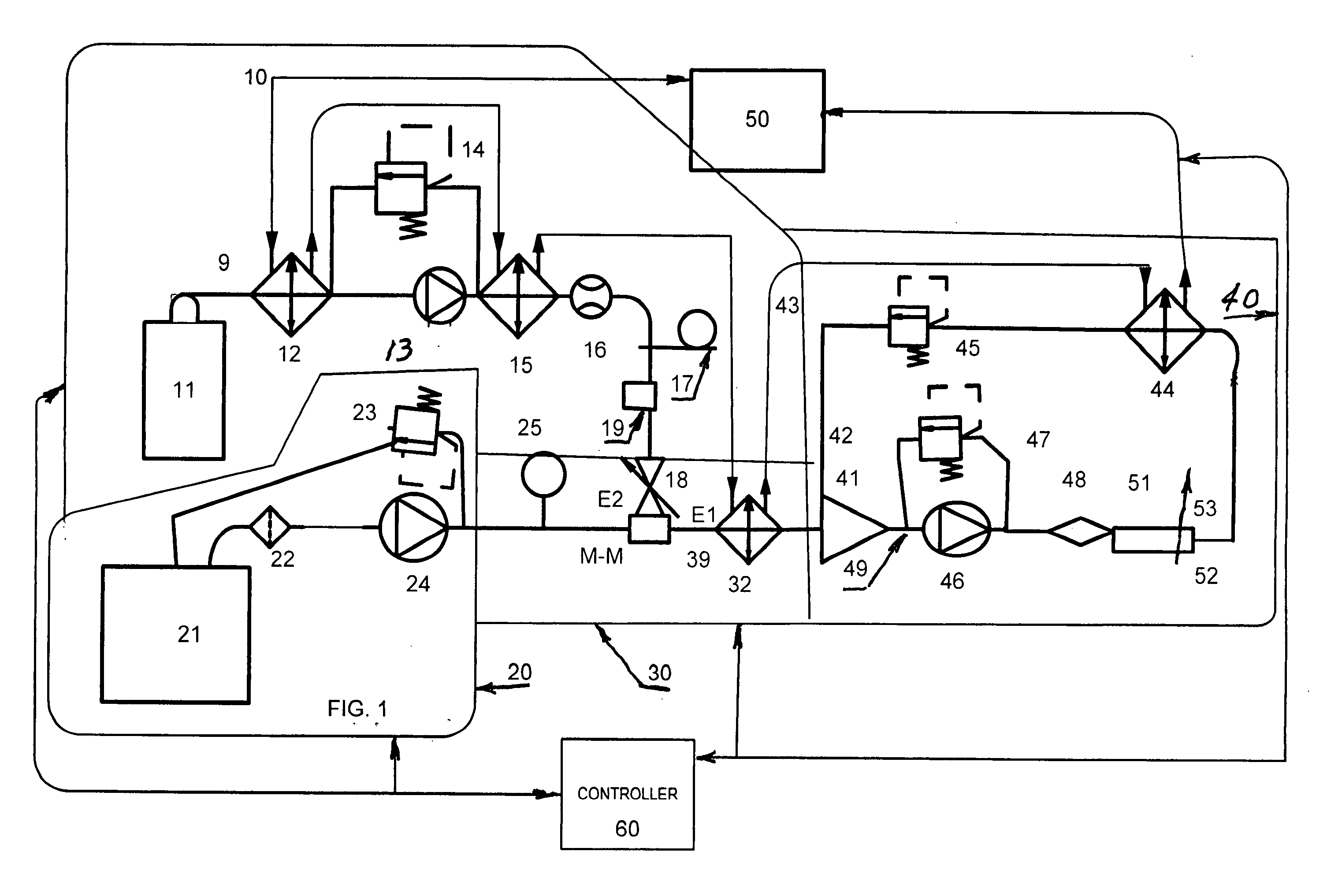
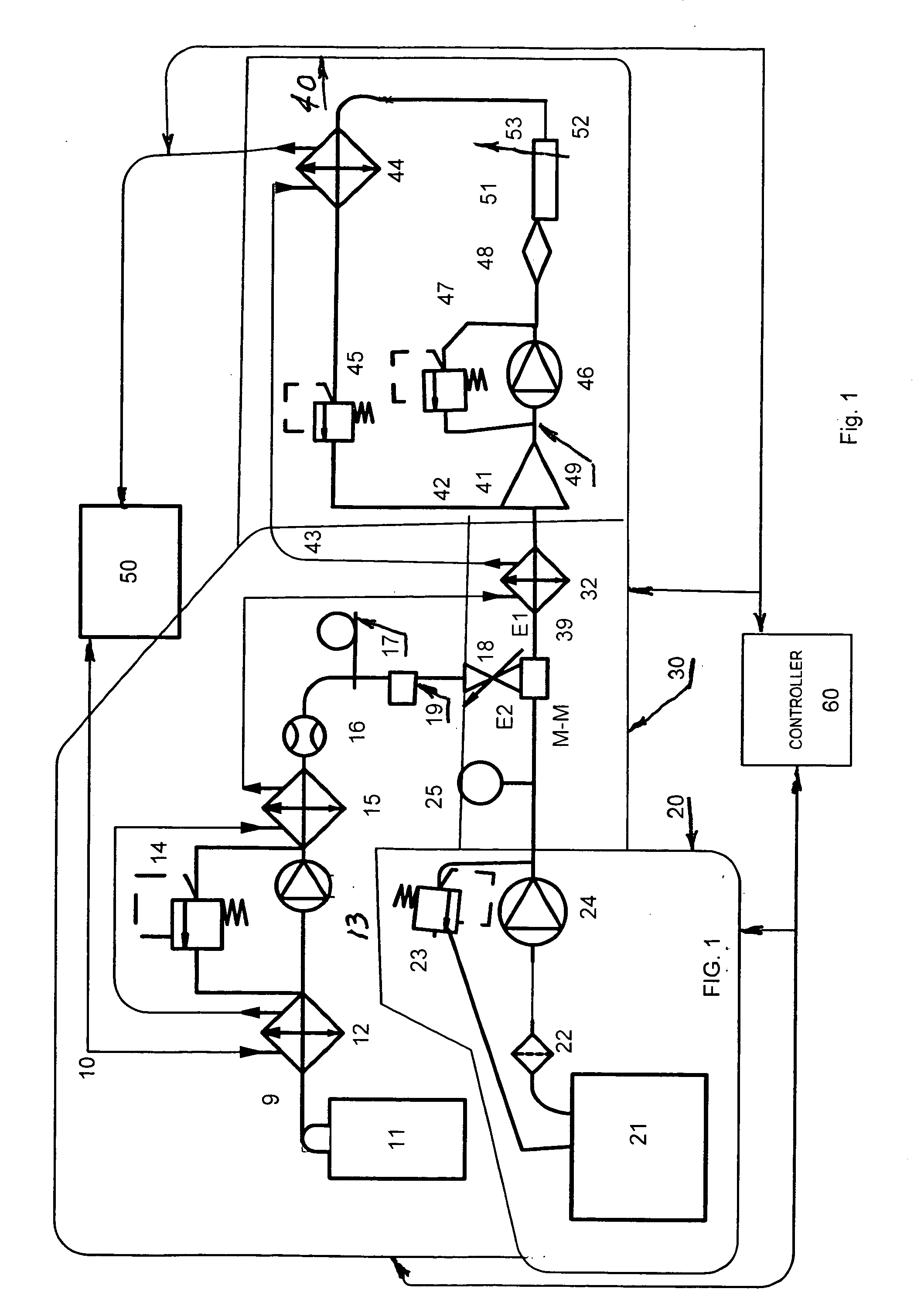
[0033]The following is a detailed description of example embodiments of the invention depicted in the accompanying drawings. The invention may take the various forms of a fuel system, a method, an energy generating device deploying the system and / or methods, which produce and deliver an ammonia / fuel oil emulsion to a conventional combustion chamber such that the ammonia is easily ignited and the ensuing flame need only travel a short distance by confining the ignition kernel within the cell.

[0034]The example embodiments are described in such detail as to clearly communicate the invention. However, the amount of detail offered is not intended to limit the anticipated variations of embodiments; on the contrary, the intention is to cover all modifications, equivalents, and alternatives falling within the spirit and scope of the present invention, as defined by the appended claims. The descriptions below are designed to make such embodiments obvious to a person of ordinary skill in the ...


PUM


Abstract

A process and apparatus is provided for burning liquid ammonia in an energy device such as a diesel engine, boiler or gas turbine. In particular, the process and apparatus include mixing a renewable fuel with a low flame speed and high ignition temperature, e.g., ammonia, with a combustible liquid fossil or bio-fuel and supplying the mixture into a closed fuel loop where part is efficiently burned in an engine combustion chamber, and part is used to cool the engine and returned by the loop for mixture with fresh incoming fuel mixture. The invention provides for the mixing and emulsifying in such a way that vapour lock is avoided. In the loop, the mixture is emulsified into a disperse distribution of fuel droplets such that upon injection of a portion into the combustion chamber, the renewable fuel in an emulsified droplet evaporates, mixes with the air and forms a small combustion cell surrounding the liquid fuel droplet. The fuel droplet burns and then serves as an ignition kernel for the gas mixture in the small combustion cell producing efficient and rapid combustion of the renewable fuel. The fuel loop allows the fuel system to automatically scale for engines varying in power output from 1 to 35,000 horsepower.

Description

BACKGROUND OF THE INVENTION[0001]The present invention broadly relates to fuel systems and, more particularly relates to a fuel system and method of forming and dispersing liquid ammonia / fuel oil emulsified droplets within a combustion volume of a conventional diesel engine, e.g., 5 hp to 35,000 hp, boiler or gas turbine to produce efficient and rapid combustion of the ammonia / fuel oil mixture comprising the fuel emulsion.[0002]At present, internal combustion engines, boilers and gas turbines, which power our cars, planes, trains and ships, and generate steam and electricity at institutional, commercial facilities and utilities, rely substantially on fossil fuels. The global supply of fossil fuels is known to be finite and experts predict that they will run dry at some time about the end of this century. It is obviously crucial to develop renewable energy sources to fuel the internal combustion engines, boilers and gas turbines to power our transportation and also the commercial and...

Claims


Application Information

Patent Timeline
IPC IPC(8): F02B43/10G05D11/02
CPCF02B47/04F02D41/0025F02M25/00F02M37/0064F02M55/00F02M2200/95Y02T10/36F02D19/0644F02D19/0684F02D19/0694F02D19/081F02M21/0287F02D19/027Y02T10/32Y02T10/30
Inventor AGOSTA, VITO
Owner CAHN RICHARD C
Why Eureka
Try Eureka