Combination cylinder with pawl-actuated emergency release device for the parking brake

a technology of emergency release device and combination cylinder, which is applied in the direction of brake cylinder, anti-theft device, braking system, etc., can solve the problems of reducing the vertical installation space affecting the stability so as to reduce the vertical installation space in the bogies, increase the force, and reduce the vertical extent of the combination cylinder

Active Publication Date: 2010-11-25
KNORR BREMSE SYST FUR SCHIENENFAHRZEUGE GMBH
View PDF8 Cites 29 Cited by
  • Summary
  • Abstract
  • Description
  • Claims
  • Application Information

AI Technical Summary

Benefits of technology

[0027]On account of the first measure, the vertical extent of the combination cylinder may be decreased because the service brake cylinder and the spring brake cylinder can be flange-mounted coaxially on one another. This may be expedient in particular because the vertical installation space in bogies may be severely restricted and more space may be available in the horizontal direction.
[0028]The second measure results in an increase in force with progressive stroke of the spring store brake piston, which leads to an advantageously high parking brake force in the end position of the spring store brake piston, and therefore in the applied state of the spring store brake. The spring store force, which itself falls with the stroke of the spring store piston, may be then compensated by the increasing force transmission ratio of the gearing. With suitable design of the gearing, it may be possible to realize an approximately constant and high store spring force on the service piston rod over the entire store of the spring store piston.

Problems solved by technology

In present-day rail vehicles, the spatial conditions in the bogies may be very restricted.
Furthermore, the installation space for the brakes may be often restricted by drive units or gauge tie bars of electromagnetic rail brakes.
These problems may be particularly pronounced if so-called combination cylinders, in which a pressure-medium-actuated service brake cylinder as a service brake and a spring store brake cylinder as a passive parking brake may be flange-mounted on one another, may be used as bogie brakes, because such combination cylinders take up a relatively large amount of installation space and may be larger than a service brake cylinder without a spring store brake cylinder.
If a rail vehicle which may be parking-braked in this way must be towed, a compressed air supply for the rail vehicle, by means of which the parking brake designed as a spring store brake can be pneumatically released, may be often not available.
In practice, the emergency release device may be also used to set the brake caliper into a force-free state during brake lining changes, since changing the brake linings with the parking brake released only pneumatically may be too unsafe, because an undesired application of the spring store brake as a result of a pressure drop poses too great a safety risk for the servicing personnel.
A disadvantage of said type of emergency release may be that its action may be slow and it requires a very long actuating travel.
A remote actuation, in order to operate the emergency release device for example from the side of the vehicle, can therefore be realized only with a great deal of difficulty.
A disadvantage of said arrangement of the torque support may be that, at all braking strokes of the spring store, a sliding movement between the bar and spindle groove takes place under force, and therefore a certain amount of wear occurs on the contact surfaces.

Method used


Image

  • Combination cylinder with pawl-actuated emergency release device for the parking brake
  • Combination cylinder with pawl-actuated emergency release device for the parking brake
  • Combination cylinder with pawl-actuated emergency release device for the parking brake

Examples


Embodiment Construction

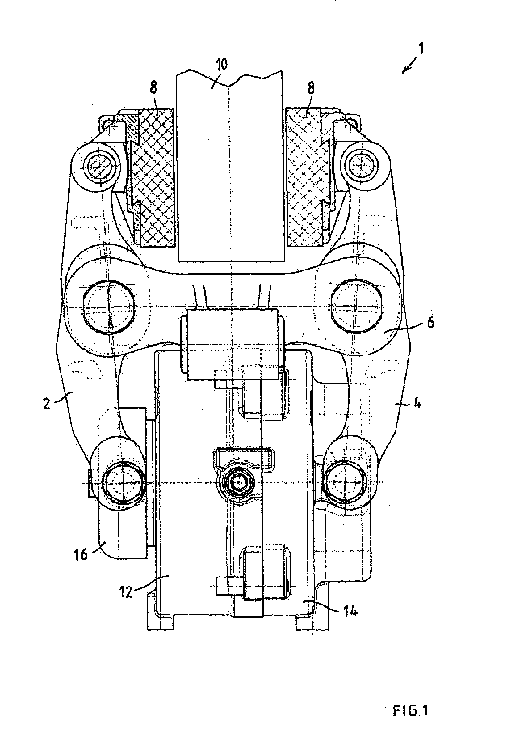
[0061]The brake caliper 1 of a rail vehicle shown in FIG. 1 has two brake caliper levers 2, 4 which run substantially parallel to one another. The two brake caliper levers 2, 4 may be articulatedly connected to one another in the central region of their longitudinal extent by a tension rod 6. The brake caliper levers 2, 4 and the tension rod 6 lie in or run parallel to a brake caliper plane which runs parallel to the drawing plane.

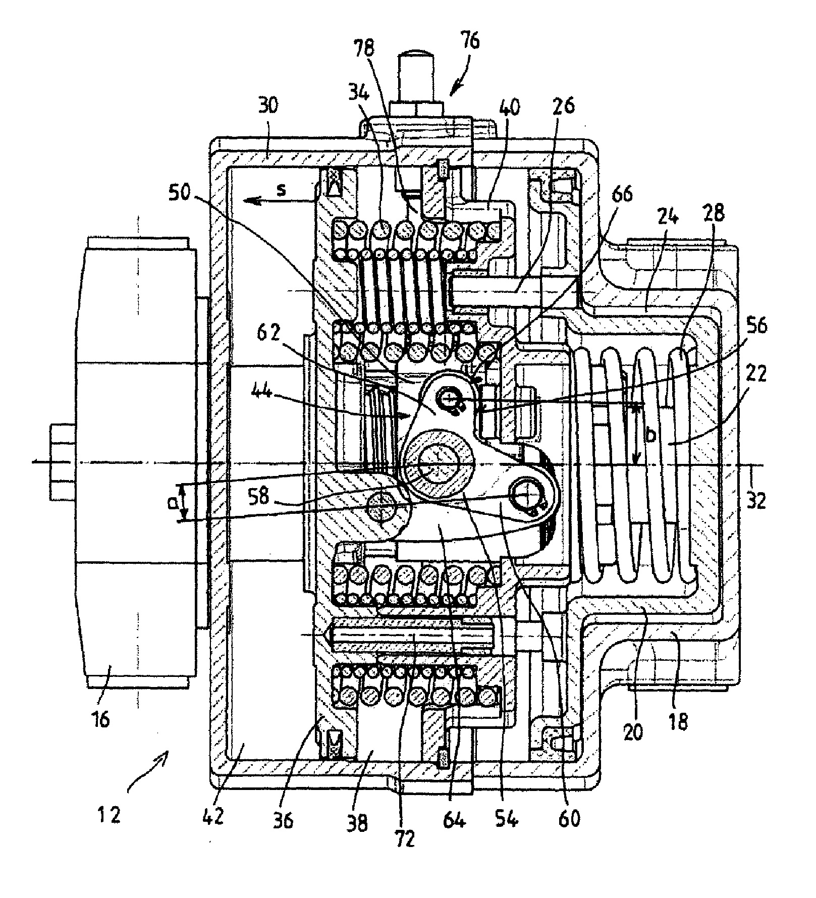
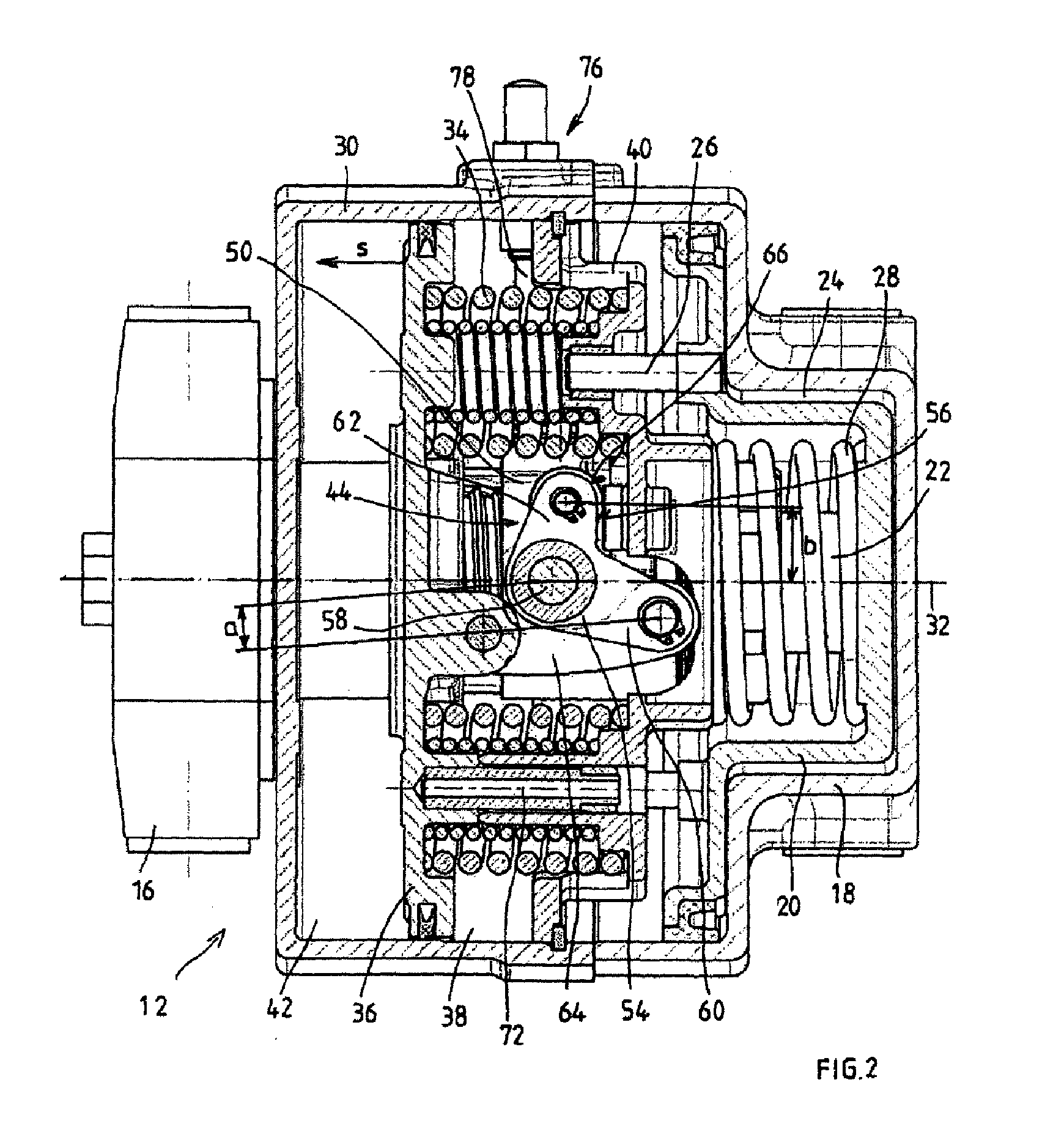
[0062]The one ends of the brake caliper levers 2, 4 bear brake pads 8 which may be articulatedly connected by means of bolts and which can engage in a frictionally locking manner into a brake disk 10. Situated between the other ends of the brake caliper levers 2, 4 is a combination cylinder 12, whose housing 14 may be articulatedly connected to one brake caliper lever 4 and whose service brake piston may be articulatedly connected via a service brake piston rod and a spindle yoke 16 to the other brake caliper lever 2.

[0063]It can be seen on the basis of FI...


PUM


Abstract

The invention relates to a combination cylinder including a service brake cylinder as an active service brake with at least one pressure-medium-actuated service brake piston which actuates a brake mechanism via a service brake piston rod, and a spring store brake cylinder as a passive parking brake with a spring store brake piston which is actuated by pressure medium counter to the action of at least one store spring, with the spring store brake piston transmitting the force of the at least one store spring to the service brake piston rod by a force-transmitting gearing in the parking braking situation. The invention provides for the gearing to be designed such that the movements of the spring store brake piston and of the service brake piston rod are coaxial and the force transmission ratio becomes greater with progressive stroke of the spring store brake piston.

Description

CROSS-REFERENCE TO RELATED APPLICATIONS[0001]The present application claims the benefit of priority to U.S. patent application Ser. No. 12 / 745,988 filed 3 Jun. 2010, which claims the benefit of priority to International Patent Application No. PCT / EP2008 / 010052 filed 27 Nov. 2008, and which further claims the benefit of priority to German Patent Application No. 10 2007 058 670.3 filed 6 Dec. 2007, the contents of which are incorporated herein by reference in their entirety.DESCRIPTIONPrior Art[0002]The present invention relates to a combination cylinder comprising a service brake cylinder as an active service brake with at least one pressure-medium-actuated service brake piston which actuates a brake mechanism via a service brake piston rod, and a spring store brake cylinder as a passive parking brake with a spring store brake piston which may be actuated by pressure medium counter to the action of at least one store spring, with the spring store brake piston transmitting the force o...

Claims


Application Information

Patent Timeline
Patent Type & Authority Applications(United States)
IPC IPC(8): F16D65/20B61H13/00F16D65/18F16D65/22F16D65/28
CPCB60T17/083B60T17/086F16D55/2245F16D65/28F16D2121/02F16D2121/12F16D2127/04F16D2125/40F16D2125/582F16D2125/64F16D2125/66F16D2125/68F16D2127/007F16D2123/00B60T17/08F16D55/224F16D65/14B61H13/00F16D65/16
Inventor KRAUS, HARRY-WERNEROSTLER, ARMINFUDERER, ERICHMATHIEU, MICHAELEBNER, CHRISTIAN
Owner KNORR BREMSE SYST FUR SCHIENENFAHRZEUGE GMBH
Why Eureka
Try Eureka