Method for packaging thermal interface materials

a thermal interface and material technology, applied in the field of packaging systems, can solve the problems of reducing the performance of electronic components, damage or shutting down of electronic components, and the difficulty in implementing the installation of relatively low-modulus tim with pick and place equipment, so as to reduce the risk of damage, reduce the surface area, and reduce the effect of modulus

Inactive Publication Date: 2010-11-25
HENKEL IP & HOLDING GMBH
View PDF87 Cites 7 Cited by
  • Summary
  • Abstract
  • Description
  • Claims
  • Application Information

AI Technical Summary

Benefits of technology

[0010]By means of the present invention, tacky products such as relatively low modulus thermal interface materials may be packaged and delivered to an installation location, and may be removed from the packaging with a significantly reduced risk of damage. The package of the present invention minimizes the surface area which operably comes into contact with the tacky product. By minimizing such contact surface area, adhesion force between the tacky product and the packaging is significantly reduced, thereby enabling efficient and non-damaging removal of the product from the packaging.

Problems solved by technology

Excess heat can reduce performance of the electronic components, and, in some cases, can lead to damage or shut down of the electronic components.
However, pick and place systems are most effective when used in connection with rigid, non-tacky structures, and efforts to implement the installation of relatively low-modulus TIM with pick and place equipment has therefore been challenging.
A primary problem encountered in this scenario is the TIM becoming wholly or partially adhered to the pick and place equipment and / or the TIM packaging.
Such adherence can damage the TIM, and can also require installation equipment shut down for cleaning.
Addition of release liners, however, increases the cost of the thermal interface pads, and requires a further process step to remove the release liner prior to attachment of a thermal diffusion structure to the electronic apparatus.
Neither of such solutions, however, address the tackiness of the thermal interface pad where the pad is stored in packaging.
Consequently, delivery of thermal interface pads to installation facilities through conventional packaging has resulted in unsatisfactory rates of TIM damage due to undesired adherence of the thermal interface pad to the packaging.
The tackiness of the relatively low modulus thermal interface pads adheres to conventional packaging systems, and inhibits efficient and damage-free removal of the thermal interface pads therefrom.

Method used


Image

  • Method for packaging thermal interface materials
  • Method for packaging thermal interface materials
  • Method for packaging thermal interface materials

Examples


example

[0047]The following example sets forth a particular embodiment of the invention. The dimensions, materials, and arrangements described in the following example, however, are exemplary only, and illustrate only one set of a variety of dimensions, materials, and arrangements contemplated by the present invention.

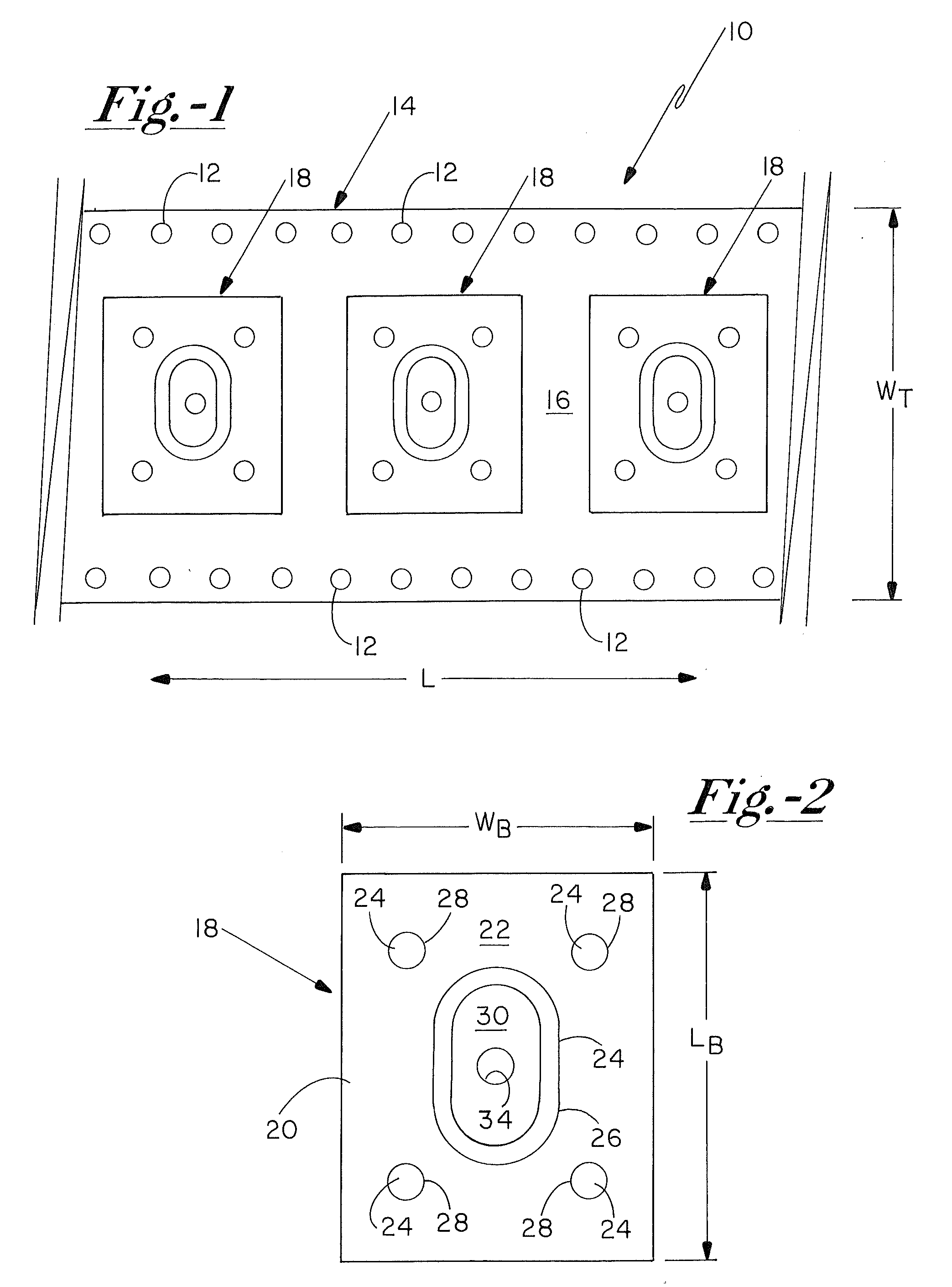
[0048]A carrier tape having a width dimension “WT” of about 24 mm was prepared from a polystyrene through a known molding process, such as a thermoforming molding process. A set of sprocket holes were punched through the carrier tape along its length and proximate to a first edge thereof. Sprocket hole spacing was set at 4 mm on center, according to an EIA standard for tape and reel package systems. A series of cavities having a spacing of 16 mm on center was provided, with each cavity having a base width dimension “WB” of 11.7 mm, and a base length dimension “LB” of 14.9 mm, wherein each base of each cavity assumed a substantially rectangular shape.

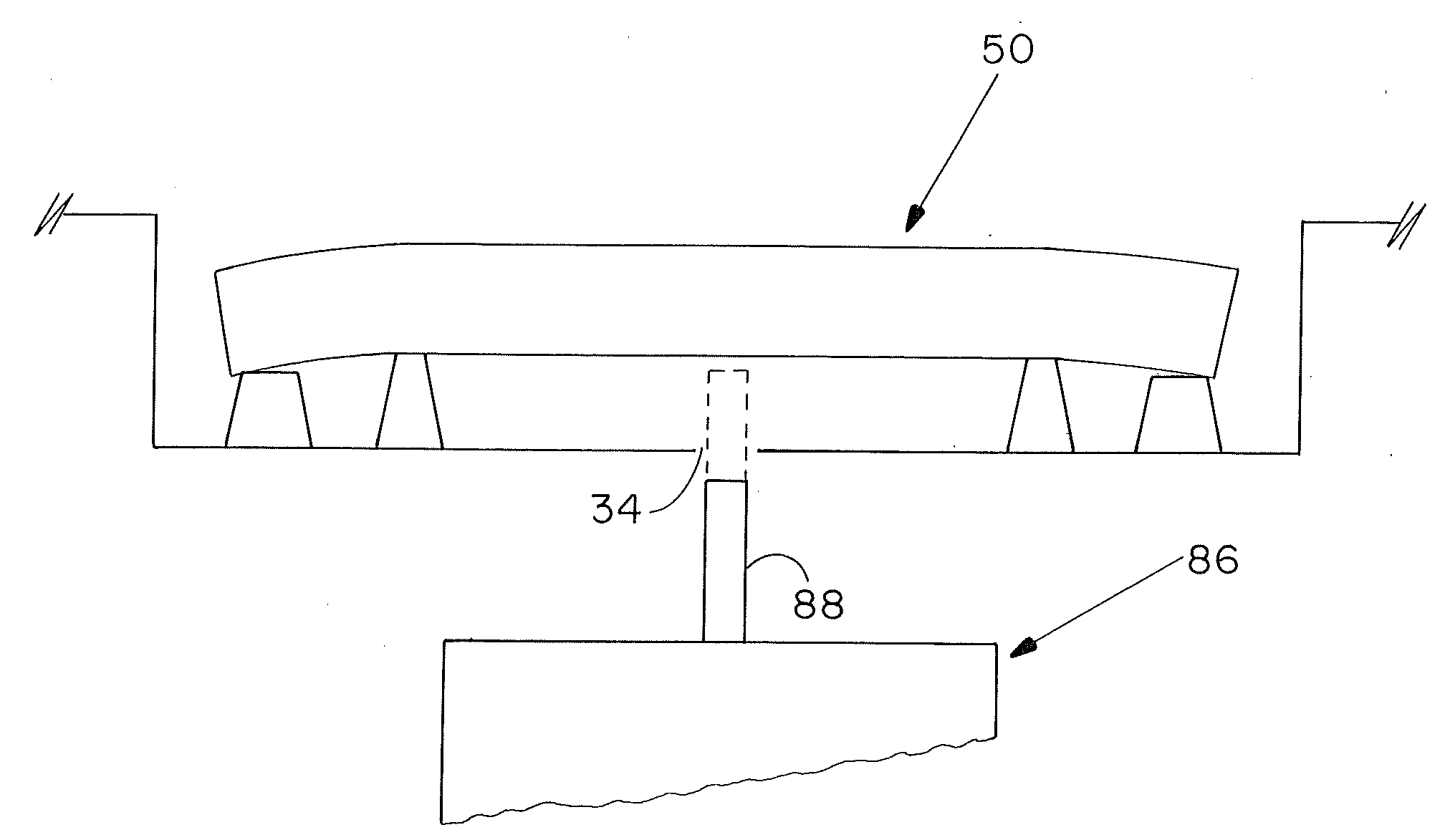
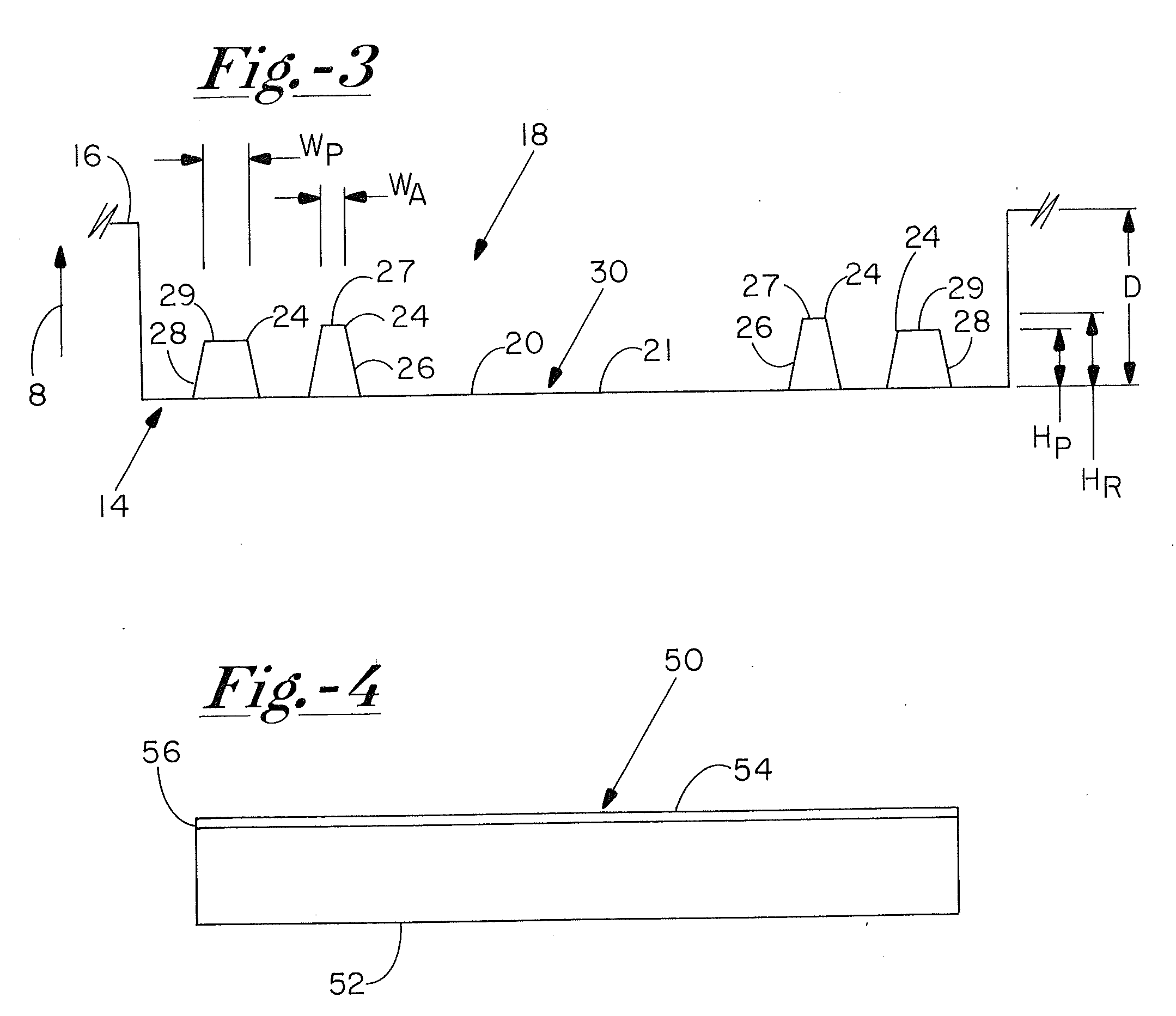
[0049]Base 20 was recessed ...


PUM

PropertyMeasurementUnit
diameteraaaaaaaaaa
thicknessaaaaaaaaaa
thicknessaaaaaaaaaa

Abstract

A package for delivery of a tacky product includes a carrier tape with a plurality of cavities separately disposed along a length thereof. Each of the cavities in the carrier tape includes a base that is sized to operably receive and support the product. The base of each cavity includes a surface profile which defines a contact surface area that is sufficiently low so as to facilitate removal of the product from the cavity without damage to the product. In some cases, the contact surface area is less than about 50% of a base surface area of the base. The carrier tape may be configured for use in tape and reel packaging systems.

Description

FIELD OF THE INVENTION[0001]The present invention relates to packaging systems generally, and more particularly to packaging systems which are configured to efficiently package and deliver a tack product, such as a conformable thermal interface material, to installation facilities. In particular, the packaging systems of the present invention enable removal of the tacky product from the package without damage or destruction to the product.BACKGROUND OF THE INVENTION[0002]Electronic components of the various type require heat transfer systems in order to remove excess heat generated in the operation thereof. Excess heat can reduce performance of the electronic components, and, in some cases, can lead to damage or shut down of the electronic components. A common electronic component in need of heat transfer systems is an integrated circuit, such as a microprocessor, which typically generates significant amounts of excess thermal energy.[0003]One mechanism for transferring excess heat ...

Claims


Application Information

Patent Timeline
Patent Type & Authority Applications(United States)
IPC IPC(8): B65D90/12B65B1/04
CPCH05K7/20472
Inventor JEWRAN, RADESHMCLNTOSH, WILLLAM E.
Owner HENKEL IP & HOLDING GMBH
Why Eureka
Try Eureka