System for converting solar radiation into electricity

a technology of solar radiation and electricity, applied in the field of power generation, can solve the problems of their cost and the cost of parabolic trough power is not yet competitive with conventional alternatives

Inactive Publication Date: 2010-11-25
MITTELMAN GUR
View PDF2 Cites 48 Cited by
  • Summary
  • Abstract
  • Description
  • Claims
  • Application Information

AI Technical Summary

Benefits of technology

[0036]Furthermore, as will be appreciated by those skilled in the art, although the options described in this embodiment for the selected criterion relate mainly to the characteristics of the first heat transfer fluid leaving the solar field, still there could be way...

Problems solved by technology

Even though solar radiation is a source of high temperature and energy at the origin, sun-earth geometrical constraints lead to a dramatic dilution of flux and to irradiance available for terrestrial of about 1 kW/m2 and consequently, to a supply of low temperature to the thermal fluid.
However, their cost is not yet competitive with conventional alternatives unless subsidized.
However, the cost of parabolic trough power is not yet competitive with conventional alternatives unless subsidized (typical installation cost for 50 MW plants is in the range of 4-6 $/W).
One of the reasons is that the standard condensing steam power block described above has several drawbacks that highly limit the overall plant cost effectiveness and deployment.
Air cooled condensers (dry cooling towers—DCT) are inferior because they increase the steam condensation temperature, and the steam condensing cycle efficiency is very sensitive to that temperature.
In addition, DCT are more expensive than WCT.
Condensing steam turbines for solar plants, typically designed to generate 50-80 MW, have a ver...

Method used


Image

  • System for converting solar radiation into electricity
  • System for converting solar radiation into electricity
  • System for converting solar radiation into electricity

Examples


Embodiment Construction

[0042]The present invention will be understood and appreciated more fully from the following detailed example taken in conjunction with the drawings.

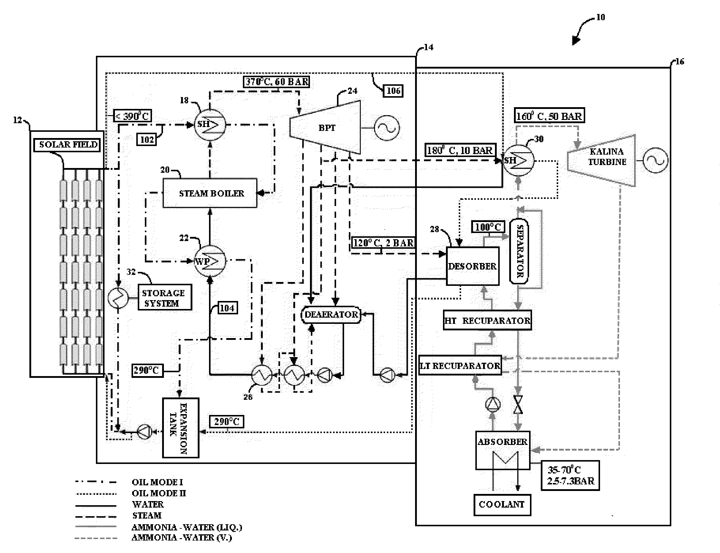
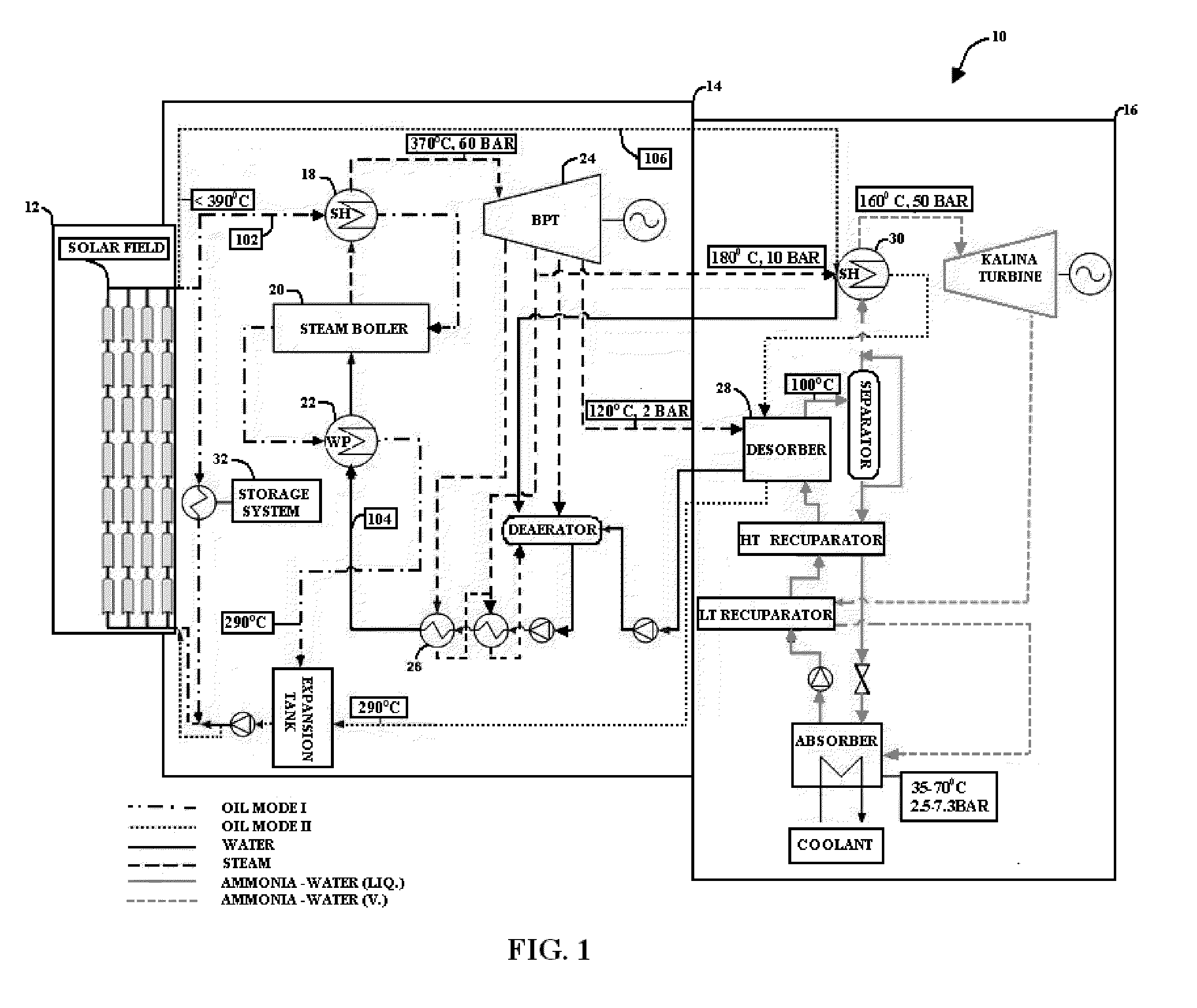
[0043]Let us consider now the example illustrated in the schematic block diagram of FIG. 1, of a system 10 designed to produce electricity from solar radiation by heating of a heat transfer media such as HTF apparatus according to an embodiment of the present invention. System 10 is a combined cycle system that comprises 3 major parts and is configured to operate in accordance with two modes of operation, depending upon the extractable thermal energy deriving from the solar source. The first part of the system, 12, is a solar field which is used for collecting solar energy and converting the collected solar energy into heat. According to this example, the solar field comprises a plurality of parabolic trough shaped collectors having pipes extending along their focal line, through which the heat transfer fluid, e.g. thermal oil, flows. T...


PUM


Abstract

A system is provided for converting thermal energy derived from a solar field into electricity. The system is adapted to operate in accordance with at least two modes of operation, depending upon the thermal energy intake, and comprises: a first power generation sub-system comprising means to heat water into superheated steam by exchanging heat with a first heat transfer fluid being heated at the solar radiation collecting field, and a back pressure turbine for producing electricity; a second power generation sub-system comprising means to heat a second working fluid, and the second working fluid is used to operate a second turbine for producing electricity; and wherein the system is characterized in that when the thermal energy received at the first power generation sub-system exceeds a predetermined threshold of a selected criterion, both power generation sub-systems are operative to produce electricity and at least part of the heat required to heat the second working fluid is derived from exhaust steam being produced at the first power generation sub-system, whereas when the thermal energy received at the first power generation sub-system does not exceed that threshold, the thermal energy conveyed by the first heat transfer fluid is used essentially to heat the second working fluid and the electricity is generated only by the second power generation sub-system.

Description

FIELD OF THE INVENTION[0001]The present invention relates in general to the field of power generation and in particularly to power blocks for Concentrated Solar thermal Power (CSP).BACKGROUND OF THE INVENTION[0002]The current global framework, with growing oil price instability, limited oil and gas resources and the Kyoto Protocol environmental requirements, calls for continued improvements in the usage of renewable energy resources, including solar. During the last decades, interest in solar energy solutions has increased because the potential of solar energy has become apparent.[0003]Even though solar radiation is a source of high temperature and energy at the origin, sun-earth geometrical constraints lead to a dramatic dilution of flux and to irradiance available for terrestrial of about 1 kW / m2 and consequently, to a supply of low temperature to the thermal fluid. It is therefore essential requisite for solar thermal power plants to make use of optical concentration devices that...

Claims


Application Information

Patent Timeline
IPC IPC(8): H02K7/18F03G6/06F01D15/10F24J2/38F24J2/34F24S50/20
CPCY02E10/46F03G6/005
Inventor RIDNIK, REFAELRODED, SHARON
Owner MITTELMAN GUR
Why Eureka
Try Eureka