Rotary vane magnetorheological (MR) energy absorber

a technology of energy absorber and magnetorheological body, which is applied in the direction of shock absorber, magnetic liquid, mechanical apparatus, etc., can solve the problems of inability to automatically adapt the energy absorption of the payload as a function of payload weight or real-time environmental measurements, and the wave-to-hull impact of high-speed watercraft. to achieve the effect of maintaining a compact profile and increasing the damper strok

Active Publication Date: 2010-12-02
INNOVITAL LLC +1
View PDF13 Cites 16 Cited by
  • Summary
  • Abstract
  • Description
  • Claims
  • Application Information

AI Technical Summary

Benefits of technology

[0009]Disclosed herein is a novel compact rotary vane MR energy absorber in which linear motion is converted into rotary motion so as to increase damper stroke while maintaining a compact profile. In this MR energy absorber, a rotor seated inside a hollow MR-fluid-filled body is equipped with “vanes” that rotate on a shaft inside the hollow body (vane herein being defined as any blade, fin or fluid foil mounted in a fixed position or movable, and extending either radially or axially with respect to an axis and operative on a fluid). The rotating vane(s) operate on the MR fluid interdependently with an internal stator (for example, a fixed vane) to propagate MR fluid flow through defined channel(s). Solenoid coils also mounted within the body control the MR fluid flow through those channels by changing the rheological properties of the fluid with the presence of a magnetic field, allowing control over the a reaction force on rotor vanes which, because the vanes are offset from the shaft, cause a reaction torque-moment on the shaft. The torque-moment serves as a damping force and can be further converted into a linear damping force with a rotary-to-linear motion converting mechanism.

Problems solved by technology

Severe shock events may include harsh vertical or crash landings of aircraft, under body explosions of military ground vehicles, horizontal collisions of automobiles, and severe wave-to-hull impact of high speed watercraft.
Lower amplitude shock and vibration tend to result from normal operation of such vehicles, including aircraft air loads or rotor loads, ground vehicles traversing rough terrain, etc.
Most current shock and vibration protection systems are passive, in that they cannot automatically adapt their energy absorption as a function of payload weight or as a function of real-time environmental measurements such as shock level, impact velocity, vibration levels, etc.
Because of this, these systems provide no isolation of vibration.
One key challenge in vehicular applications involving MR energy absorbers is the device weight and size associated with providing sufficient stroke and force capability.
Often, a large and massive energy absorbing device is not a possibility due to design and structural constraints.
The size and weight of these conventional linear-piston MR damper designs for such applications can make their use prohibitive.

Method used


Image

  • Rotary vane magnetorheological (MR) energy absorber
  • Rotary vane magnetorheological (MR) energy absorber
  • Rotary vane magnetorheological (MR) energy absorber

Examples


first embodiment

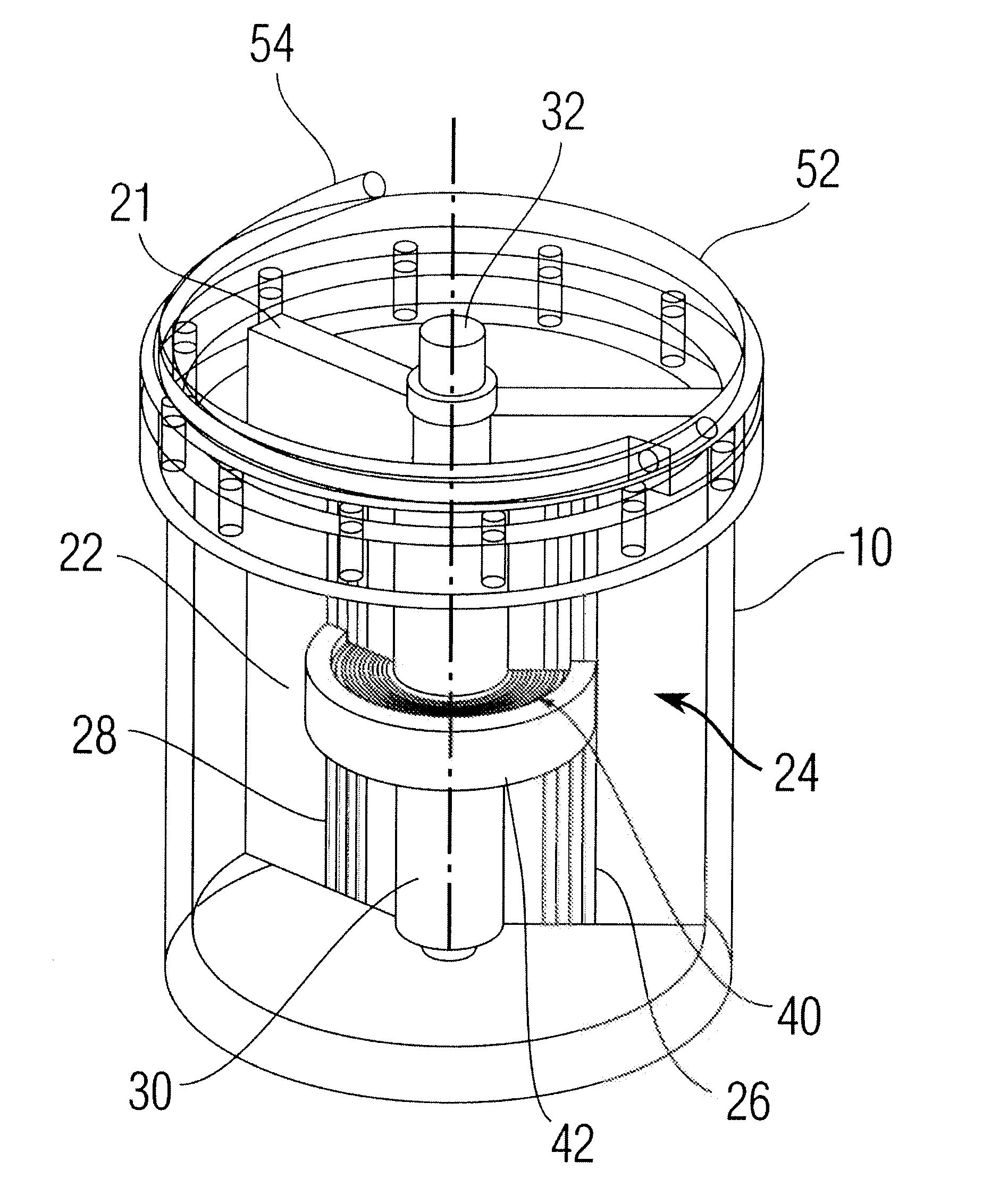
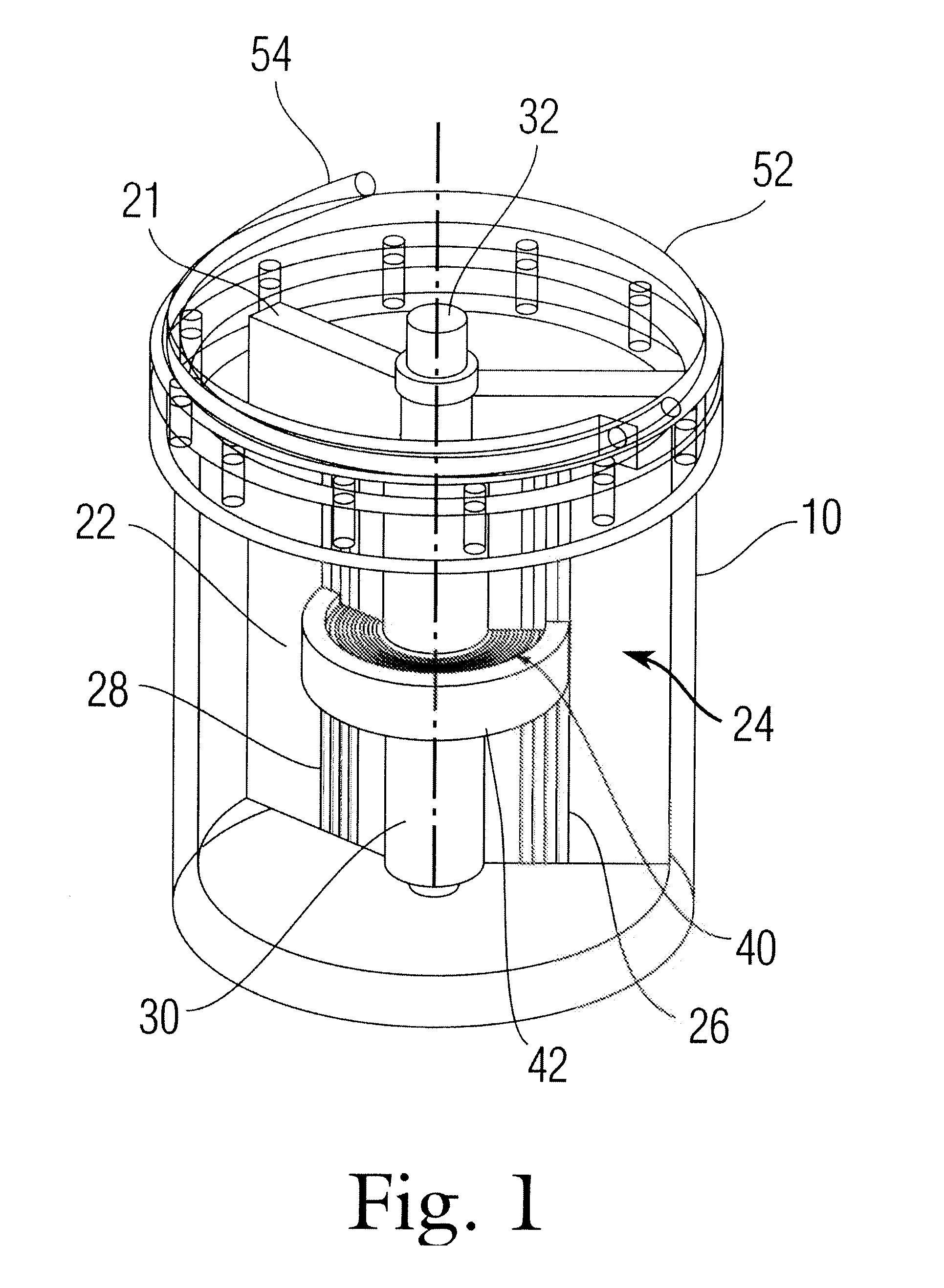
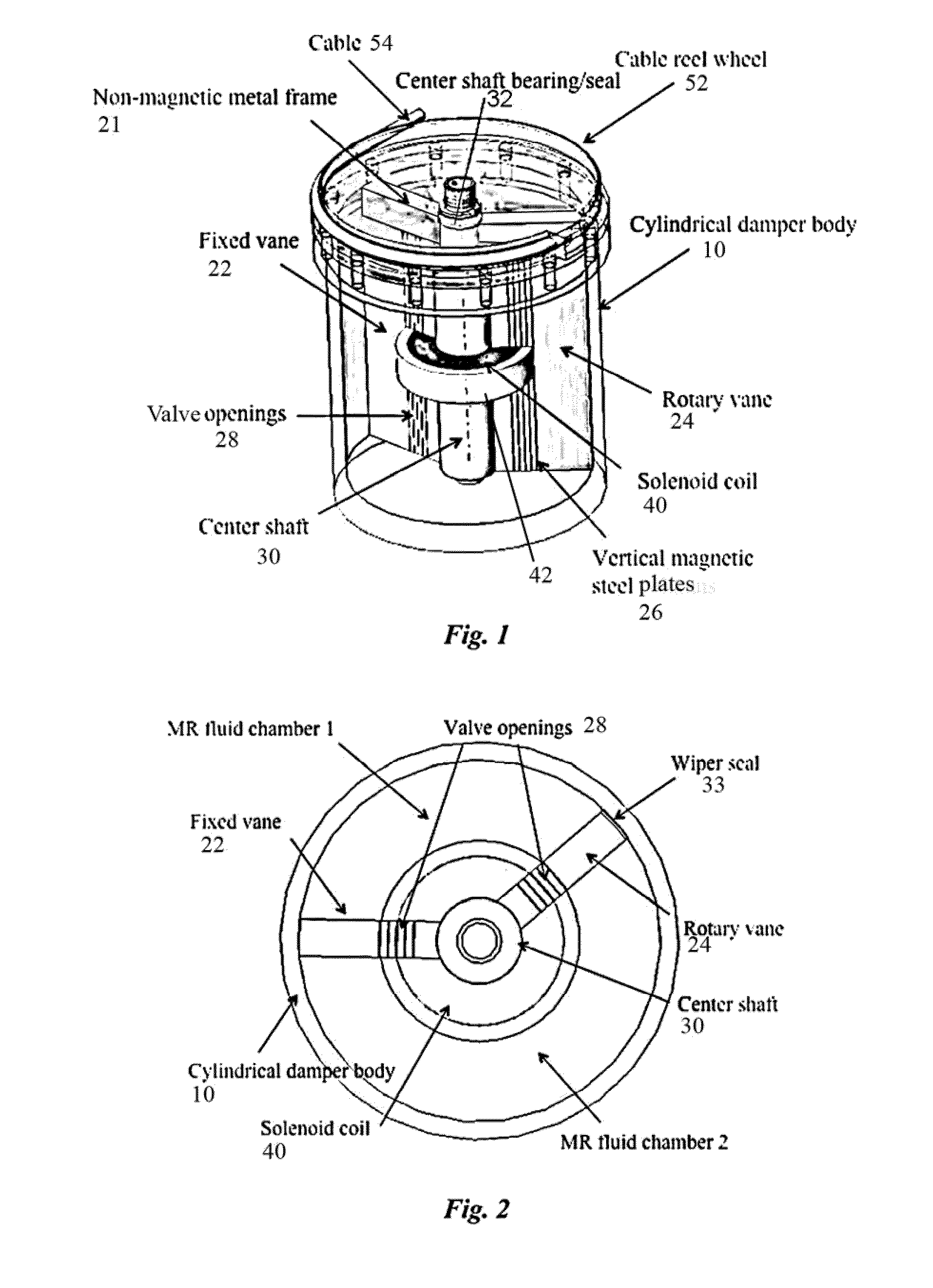
[0032]the rotary vane MREA of the present invention is depicted in FIG. 1. In this embodiment, the MREA comprises a cylindrical damper body 10 defining an internal cylindrical volume containing MR fluid. An internal stator comprising one or more fixed vane structures 22 protrudes radially into the internal volume of damper body 10. A shaft 30 is rotatably mounted in the damper body 10 and traverses the internal volume and one or more rotary vane structures 24 protrude radially from the shaft 30 within the cylindrical volume. In addition, a rotation / linear motion converting mechanism (here a cable reel including a cable reel wheel 52 equipped with a cable 54) is coupled to the shaft 30. Both vanes 22, 24 are rectangular structures seated radially across the cylindrical volume, and the rotary vane 24 is driven by the center shaft 30 which is made of magnetic steel. Each vane 22, 24 is made of vertical magnetic steel plates 26 arranged in columns and mounted in parallel within a non-ma...

second embodiment

[0037]Referring to FIG. 3, the invention is a rotary vane MREA with an external by-pass valve body 60, rather than internal valve openings 28. This embodiment likewise comprises a cylindrical damper body 10 with an internal cylindrical volume, fixed / rotary vane structures 22, 24, a rotation / linear motion converting mechanism (cable reel 52 and cable 54). The by-pass valve body 60 is external to body 30 and forms a conduit in which a rectilinear flow valve 62 is embedded. The vane structure may be identical, similarly including a fixed vane 22 and a rotary vane 24. Both vanes 22, 24 are rectangular and seated across the radial direction of the cylindrical volume, and between the fixed and rotary vane 22, 24 is a center shaft 30. The vane structures 22, 24 and center shaft 30 can be made of light metal materials, but there are no valve openings on or in the vanes themselves (as ref. 28 in FIGS. 1-2). The boundary edges of the fixed vane 22 are integrated with the internal surface of t...

fourth embodiment

[0044]the rotary vane MREA comprises one or more axially-mounted rotary vane(s) mounted on the shaft (rather than radial vanes 24, and a cooperating stator structure, which operate by a shear motion rather than pressure differential. The axially-mounted rotary vane(s) shear through the MR fluid, and shear resistance creates a torque-moment and damping force. A solenoid-induced magnetic field controls the shear resistance to rotation of the axially-mounted rotary vane(s), as before allowing control over the torque moment on rotor and shaft. The torque-moment can be further converted into a linear damping force with a rotary-to-linear motion converting mechanism.

[0045]The fourth embodiment of the rotary vane MREA of the present invention is depicted in the perspective drawing of FIG. 7. In this embodiment, the MREA comprises a cylindrical damper body 10 defining an internal cylindrical volume containing MR fluid. The cylindrical damper body 10 may or may not be equipped (or formed) wi...


PUM

PropertyMeasurementUnit
magnetic fieldaaaaaaaaaa
internal volumeaaaaaaaaaa
pressureaaaaaaaaaa

Abstract

A rotary vane magnetorheological energy absorber, which enables a longer stroke capability in a more compact configuration than conventional magnetorheological devices, is disclosed. This novel device design is attractive for applications where long stroking capability, high force dynamic range, device size, and device weight are important. The improved magnetorheological energy absorber comprises an internal or external flow valve and a hollow body enclosing fixed and rotary vanes as well as magnetorheological fluid. Fluid flow in the valve is restricted as a solenoid is activated, thus adjusting the capability of the device to react torque. Various flow valve configurations are disclosed, as well as various motion translation mechanisms for translating linear motion to rotary motion for use of the rotary vane magnetorheological energy absorber. The improved design minimizes the amount of magnetorheological fluid required as compared to conventional linear stroke energy absorbers, thus minimizing device weight.

Description

CROSS-REFERENCE TO RELATED APPLICATION(S)[0001]The present application derives priority from U.S. provisional patent application 61 / 268,419 filed 12 Jun. 2009, and is a continuation-in-part of U.S. application Ser. Nos. 11 / 818,582 and 12 / 378,275.BACKGROUND OF THE INVENTION[0002]1. Field of the Invention[0003]The present invention relates generally to energy absorbers and energy absorption systems, and more particularly, to a rotary magnetorheological damper for shock and vibration energy absorption systems.[0004]2. Description of Prior Art[0005]The primary function of a shock and vibration protection system is to minimize the potential for equipment damage and / or personnel injury during shock and vibration loading. Such systems are important for vehicular applications, including aircraft, ground vehicles, marine vehicles, etc. Severe shock events may include harsh vertical or crash landings of aircraft, under body explosions of military ground vehicles, horizontal collisions of auto...

Claims


Application Information

Patent Timeline
Patent Type & Authority Applications(United States)
IPC IPC(8): F16F9/53H01F1/44
CPCF16F9/537F16F9/3415
Inventor HIEMENZ, GREGORY J.HU, WEINGATU, GRUMWERELEY, NORMAN MARK
Owner INNOVITAL LLC
Why Eureka
Try Eureka