Solar inverter and control method

Active Publication Date: 2010-12-02
GENERAL ELECTRIC CO
View PDF18 Cites 55 Cited by
  • Summary
  • Abstract
  • Description
  • Claims
  • Application Information

AI Technical Summary

Benefits of technology

[0004]In accordance with an exemplary embodiment of the present invention, a power generation system is provided. The system comprises a photovoltaic module for generating direct current (DC) power and a controller to determine a maximum power point for the power generation system. The system further includes a boost converter for receiving control signals from the controller to boost the power from the PV module to a threshold voltage required to inject sinusoidal currents into the grid and a DC to alternating current (AC) multilevel inverter to supply the power from the PV module to a power grid. A bypass circuit is also provided in the system to bypass the boost converter when an input voltage of the DC to AC multilevel inverter is higher than or equal to the threshold voltage.
[0005]In accordance with an

Problems solved by technology

Power losses of the power electronic converters are an important issue in unit sizing of photovoltaic systems because of the influence of such losses on the total energy delivered to the load.
The power losses occur in the converters mainly because of losses in switching devices such as Insulated Gate Bipolar Transistors (IGBTs), Metal Oxide Field Effect Transistors (MOSFETs) and diodes, which are generally used in the converters or passive components such as filter inductors.
The switching devices generally have three major types of losses: conductio

Method used


Image

  • Solar inverter and control method
  • Solar inverter and control method
  • Solar inverter and control method

Examples


Embodiment Construction

[0013]As discussed in detail below, embodiments of the present invention function to provide a system and a method for efficient power transfer from a solar power generation system to a load or a power grid.

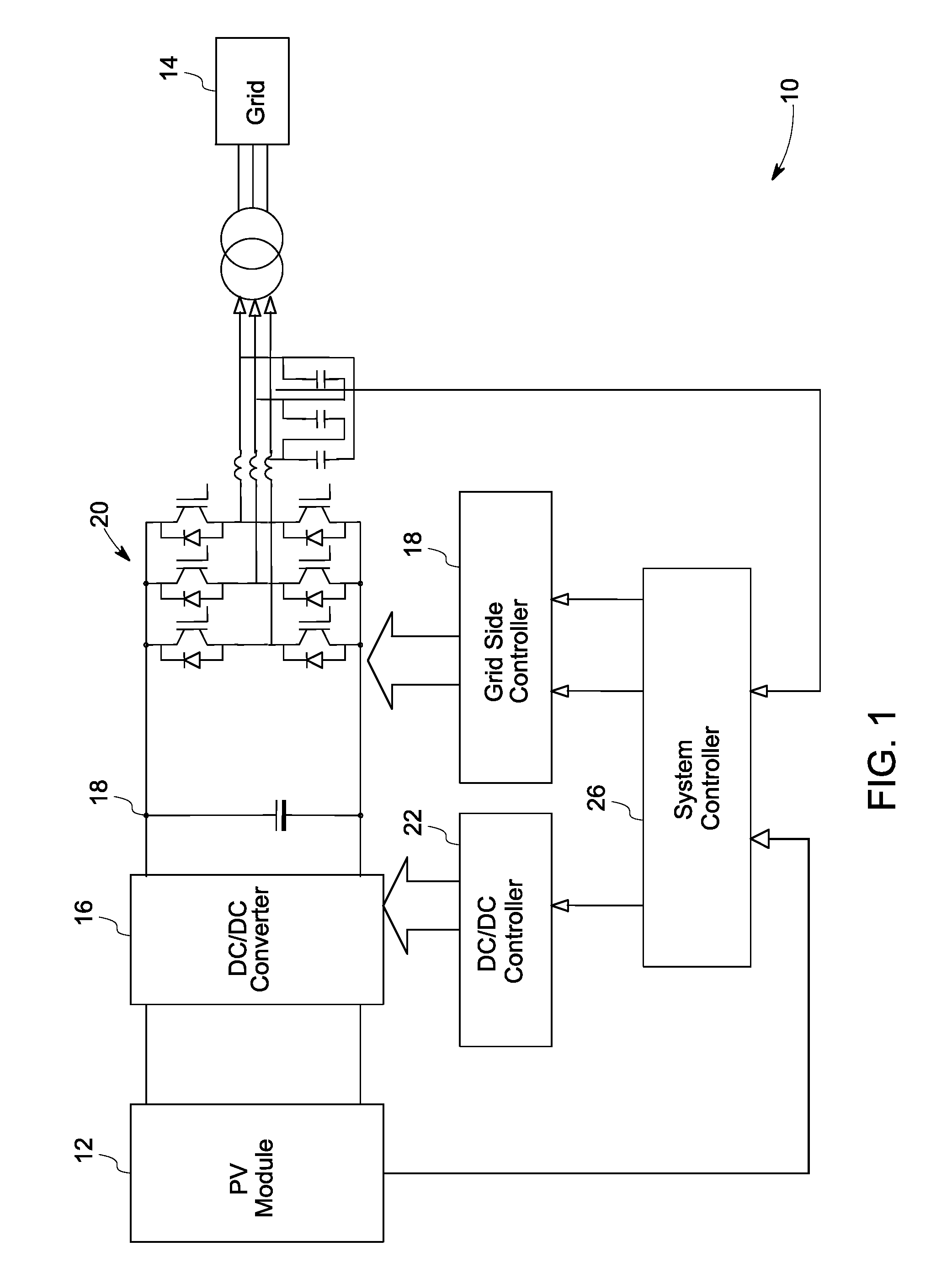
[0014]FIG. 1 illustrates a conventional solar power generation system 10. The power generation system includes a PV module 12. The PV module is connected to a power grid 14 through a DC / DC converter 16, a DC link 18 and a grid side three-phase DC / AC converter 20. The DC / AC converter 20 maintains a constant DC voltage at the DC link 18, and thus the energy flow from the DC-LINK 18 to the power grid 14 is managed. The DC / DC converter 16 is controlled by a controller 22, and the grid side converter 20 is controlled by a grid side controller 24. A system controller 26 generates a reference DC voltage command, a reference output voltage magnitude command, and a reference frequency command for the DC / DC converter 22 and grid side converter 20. In other systems, the grid side three-phas...


PUM


Abstract

A power generation system including a photovoltaic (PV) module to generate direct current (DC) power is provided. The system includes a controller to determine a maximum power point for the power generation system and a boost converter for receiving control signals from the controller to boost the power from the PV module to a threshold voltage required to inject sinusoidal currents into the grid. A DC to alternating current (AC) multilevel inverter is provided in the system to supply the power from the PV module to a power grid. The system also includes a bypass circuit to bypass the boost converter when an input voltage of the DC to AC multilevel inverter is higher than or equal to the threshold voltage.

Description

BACKGROUND[0001]This invention relates generally to electric energy conversion, and, more specifically, to efficient connection of a photovoltaic module to a power grid or a load.[0002]With the rising cost and scarcity of conventional energy sources and concerns about the environment, there is a significant interest in alternative energy sources such as solar power and wind power. Solar power generation uses photovoltaic (PV) modules to generate electricity from the sun. Multiple PV cells are connected electrically to one another in such systems. The electricity generated by PV modules is transmitted to the power grid through one or multiple power electronic converters.[0003]Power losses of the power electronic converters are an important issue in unit sizing of photovoltaic systems because of the influence of such losses on the total energy delivered to the load. The power losses occur in the converters mainly because of losses in switching devices such as Insulated Gate Bipolar Tr...

Claims


Application Information

Patent Timeline
IPC IPC(8): H02M7/44
CPCG05F1/67H01L31/02021H02J3/383H02J3/385H02M7/487H02M2001/007Y02E10/563Y02E10/58H02J2300/26H02J2300/24H02J3/381Y02E10/56H02M1/007
Inventor O'BRIEN, KATHLEEN ANNTEICHMANN, RALPH
Owner GENERAL ELECTRIC CO
Why Eureka
Try Eureka