Light control film

a light control film and film matrix technology, applied in the field of light control films, can solve the problems of poor the adhesiveness between the film matrix and the substrate is not molecule-designed, and the substrate is very easily peeled, so as to achieve stable light control function and high adhesiveness

Active Publication Date: 2010-12-09
RESONAC CORP
View PDF15 Cites 26 Cited by
  • Summary
  • Abstract
  • Description
  • Claims
  • Application Information

AI Technical Summary

Benefits of technology

[0009]An object of the invention is to provide a light control film wherein the adhesiveness between a film matrix and substrates is improved so that a stable light control function is exhibited.
[0026]The light control film of the invention is high in the adhesiveness between the light control layer and the transparent electroconductive resin substrates to make it possible to exhibit a stable light control function.

Problems solved by technology

However, the polymeric resin, which is cured to be turned into a film matrix, is not molecule-designed, considering the adhesiveness onto the transparent electroconductive substrates.
Thus, the adhesiveness between the film matrix and the substrates such as a PET film having a surface on which an electroconductive thin film made of ITO or the like is formed, is poor, and there remains a problem that the substrates are very easily peeled.

Method used


Image

  • Light control film
  • Light control film
  • Light control film

Examples


example 1

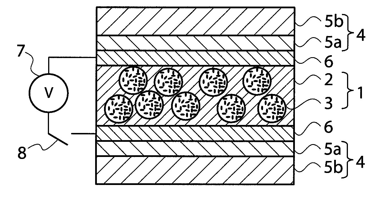
[0147]The light control suspension yielded in the item (Production Example of Light Control Suspension), the weight of which was 2.5 g, was added to 10 g of the energy ray curable silicone resin yielded in the item (Production Example of Energy Ray Curable Silicone Resin), 0.2 g of bis(2,4,6-trimethylbenzoyl)phenylphosphine oxide (manufactured by Ciba Specialty Chemicals Inc.) as a polymerization initiator, and 0.3 g of dibutyltin dilaurate as an anti-coloring agent. The liquid was mechanically stirred for 1 minute to produce a light control material.

[0148]Separately, a Mayer bar coating method was used to apply a solution wherein PM-21 (Nippon Kayaku Co., Ltd.) having a structure illustrated below, as a phosphoric diester, was dissolved in methyl ethyl ketone to give a concentration of 0.3% by mass onto the whole of a surface of a polyester film (TETOLIGHT TCF, manufactured by Oike & Co., Ltd., thickness: 125 μm), the surface electric resistance value of the film being from 200 to ...

example 2

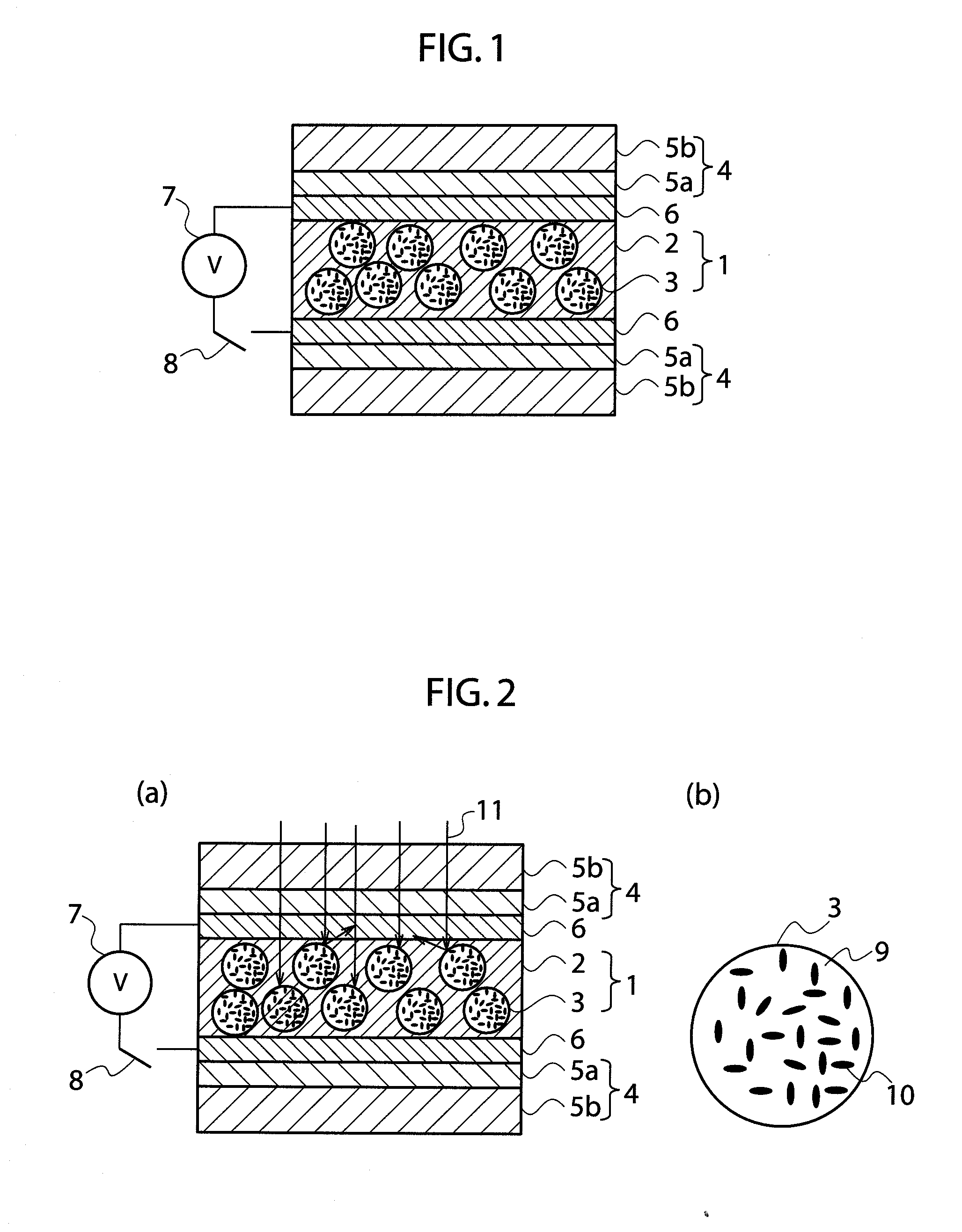
[0168]Light control films were produced and various properties thereof were measured in the same way as in Example 1 except that the solution when the primer layers were formed was changed to 0.5, 1.0, 5.0 and 10% by mass solutions of PM-21 (Nippon Kayaku Co., Ltd.) used as a phosphoric diester in methyl ethyl ketone, respectively. The thicknesses of the formed primer layers were 3 nm (0.5% by mass), 22 nm (1.0% by mass), 89 nm (5.0% by mass), and 162 nm (10% by mass), respectively.

example 3

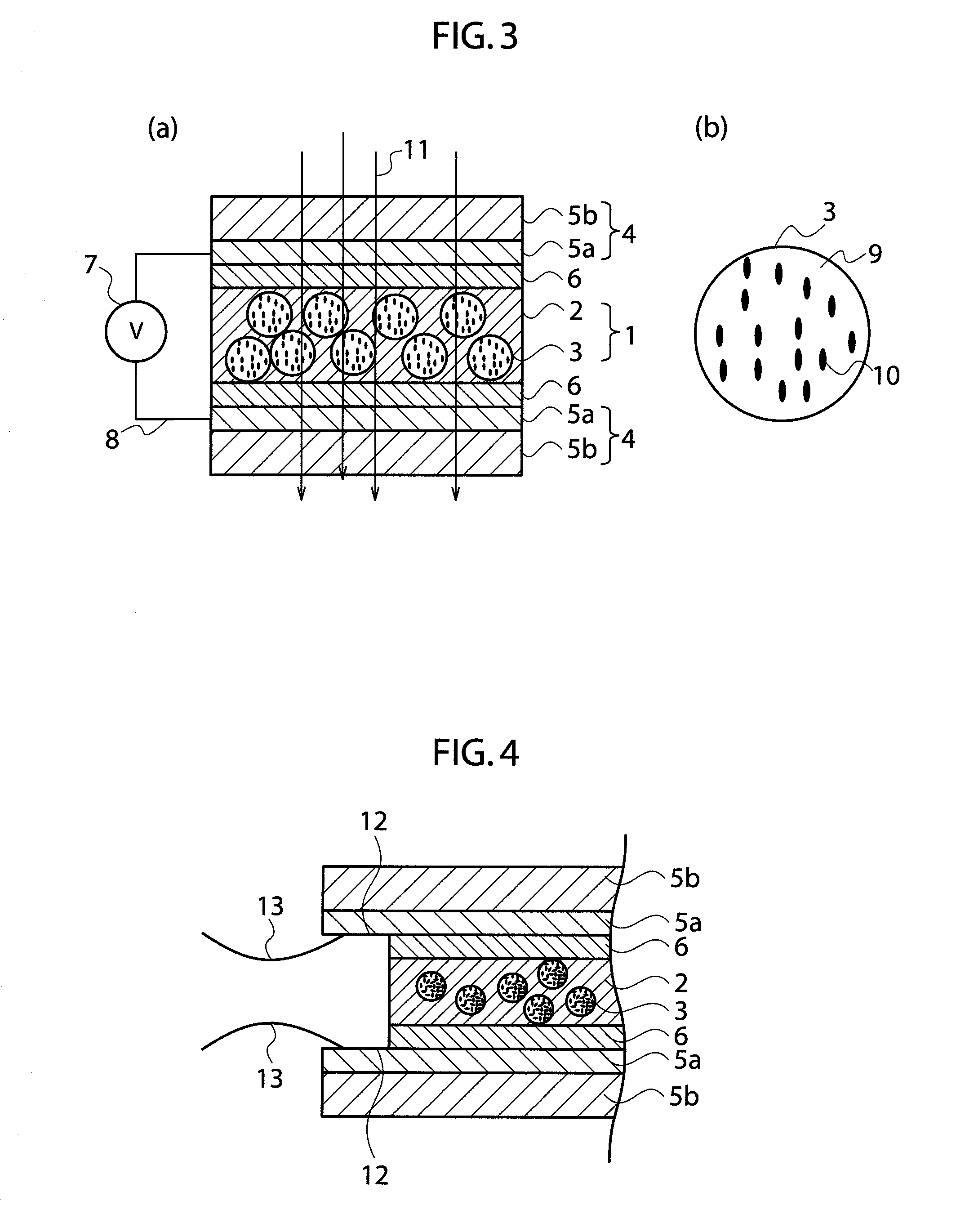
[0169]A light control film was produced and various properties thereof were measured in the same way as in Example 1 except that the solution when the primer layers were formed was changed to a 0.3% by mass solution of P-2M (Kyoeisha Chemical Co., Ltd.) having a structure illustrated below, which was used as a phosphoric diester, in methyl ethyl ketone. The thickness of each of the formed primer layers was measured by use of a spectroscopic ellipsometer, M-2000D (manufactured by J. A. Woolam Japan Co., Inc.). As a result, the thickness was 3 nm.


PUM

PropertyMeasurementUnit
thicknessaaaaaaaaaa
thicknessaaaaaaaaaa
thicknessaaaaaaaaaa

Abstract

Disclosed is a light control film comprising:two transparent electroconductive resin substrates; anda light control layer sandwiched between the two transparent electroconductive resin substrates, the light control layer containing:a resin matrix; anda light control suspension dispersed in the resin matrix,wherein the light control film has a primer layer on the light control layer side of at least one of the transparent electroconductive resin substrates, and the primer layer is formed by using a phosphoric ester having in the molecule thereof one or more polymerizable groups. By virtue of the above constitution, the light control film has an improved adhesion between a film matrix and a substrate, and has a stable light control function.

Description

FIELD OF THE INVENTION[0001]The present invention relates to a light control film having a light control function.BACKGROUND OF THE INVENTION[0002]The light control glass containing a light control suspension is a glass invented unprecedentedly by Edwin Land (U.S. Pat. No. 1,955,923 and U.S. Pat. No. 1,963,496 specifications), and the form thereof has a structure wherein a light control suspension in a liquid state is injected into a narrow gap between two transparent electroconductive substrates. According to the invention by Edwin Land, in the liquid light control suspension injected into the gap between the two transparent electroconductive substrates, most of incident light is reflected, scattered or absorbed on or into light control particles dispersed in the suspension by Brownian motion of the light control particles when no electric field is applied to the suspension. Thus, only a very slight portion thereof is transmitted therethrough.[0003]In other words, the degree of the...

Claims


Application Information

Patent Timeline
Patent Type & Authority Applications(United States)
IPC IPC(8): G02F1/01
CPCG02F2202/28G02F1/172
Inventor NOMURA, SATOYUKIMORISHITA, YOSHIITANAKA, TOORU
Owner RESONAC CORP
Why Eureka
Try Eureka