Eureka AIR delivers breakthrough ideas for toughest innovation challenges, trusted by R&D personnel around the world.

Plodder machine

a technology of a plodder and a blade is applied in the field of plodders, which can solve the problems of low product productivity, increased time and labor costs for subsequent product cleaning, and increased production costs of environment-friendly charcoal, so as to reduce the time and labor costs needed for subsequent product cleaning. , the effect of increasing the productivity per unit tim

Inactive Publication Date: 2010-12-09
LAI KUEI TSAI
View PDF37 Cites 3 Cited by
  • Summary
  • Abstract
  • Description
  • Claims
  • Application Information

AI Technical Summary

Benefits of technology

[0007]A primary object of the present invention is to provide an improved plodder machine to enable increased productivity per unit time.
[0009]A further object of the present invention is to provide an improved plodder machine capable of automatically collecting and separating raw material fragments from the bar-shaped products to save the time and labor costs for cleaning the products, and to recycle the raw material fragments.
[0011]The forming member further includes a heater for preheating the forming holes and accordingly forming the bar-shaped products in the forming holes. In an operable embodiment, the heater is a heating coil wound around an outer periphery of the forming member. In another operable embodiment, the heater includes heating coils provided inside the forming member to surround the forming holes to reduce heat energy loss at outer periphery of the forming member and provide improved heat transfer.
[0017]In the plodder machine of the present invention, the horizontally rotating rolling device can sequentially press the raw material into a large number of circularly arranged forming holes to enabled increased productivity per unit time. And, by changing the forming sleeves, it is able to produce bar-shaped products of different cross-sectional shapes and sizes to meet different demands. Moreover, with the screening discharging device provided with a screen and a vibrator, raw material fragments discharged from the forming holes onto the screen along with the produced bar-shaped products can be shaken to pass through the screen holes and completely fall to the slant collecting chute for recycling. Therefore, the time and labor costs needed for subsequent product cleaning can be reduced, and the usable raw material fragments can be recycled without being wasted.

Problems solved by technology

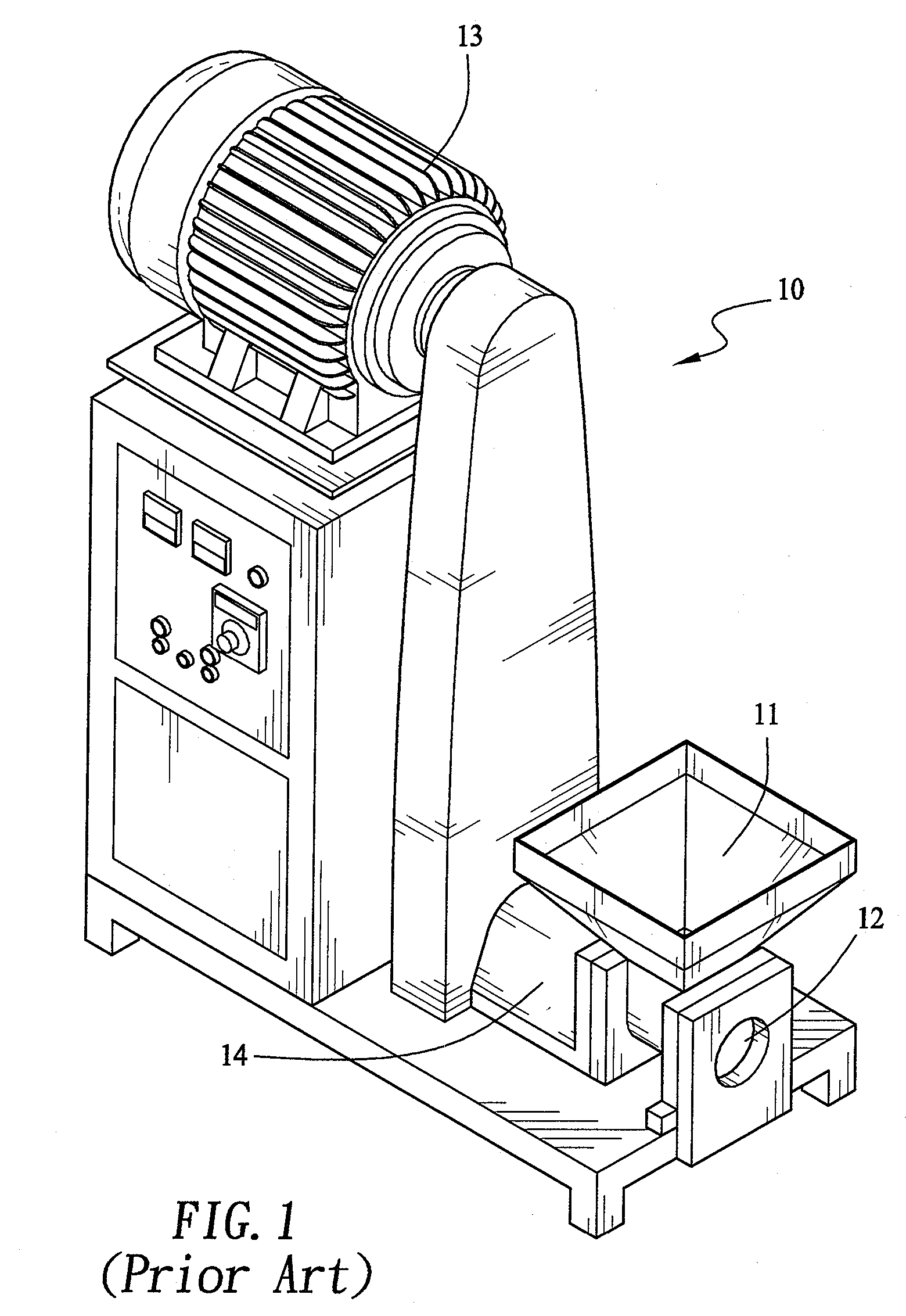
The conventional plodder machine 10 has the following disadvantages: (1) the one-way compression and one-way discharging structure thereof largely restricts the production rate, and the productivity thereof is low and ranged only from 0.18 tons to 0.24 tons per hour; (2) the discharge port 12 has fixed size and shape that could not be freely replaced or changed; and (3) there is not any platform provided outside the discharge port 12 for receiving the discharged products, and the discharged products tend to become damaged or defective when falling on the ground.
However, in the practical manufacturing process, some raw material fragments are frequently discharged via the discharge port along with the compressed products and fall on the discharging chute.
These raw material fragments tend to attach to the surfaces of the compressed products and additional labor and time is required to remove the raw material fragments from the products to thereby form unnecessary increase in the manufacturing cost of the environment-friendly charcoal.

Method used


Image

  • Plodder machine
  • Plodder machine
  • Plodder machine

Examples


Embodiment Construction

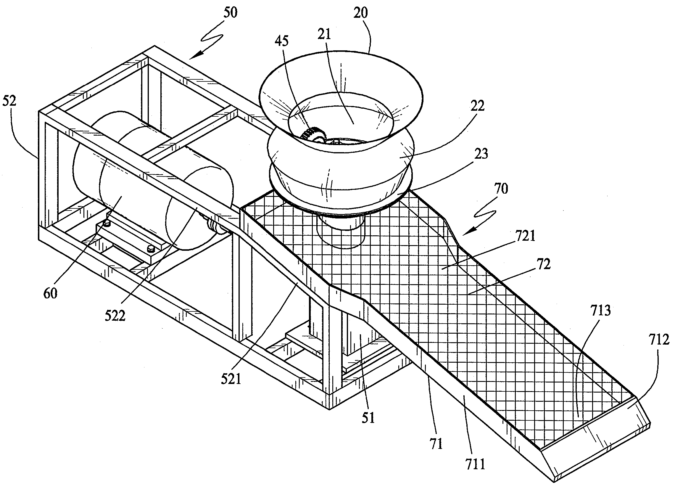
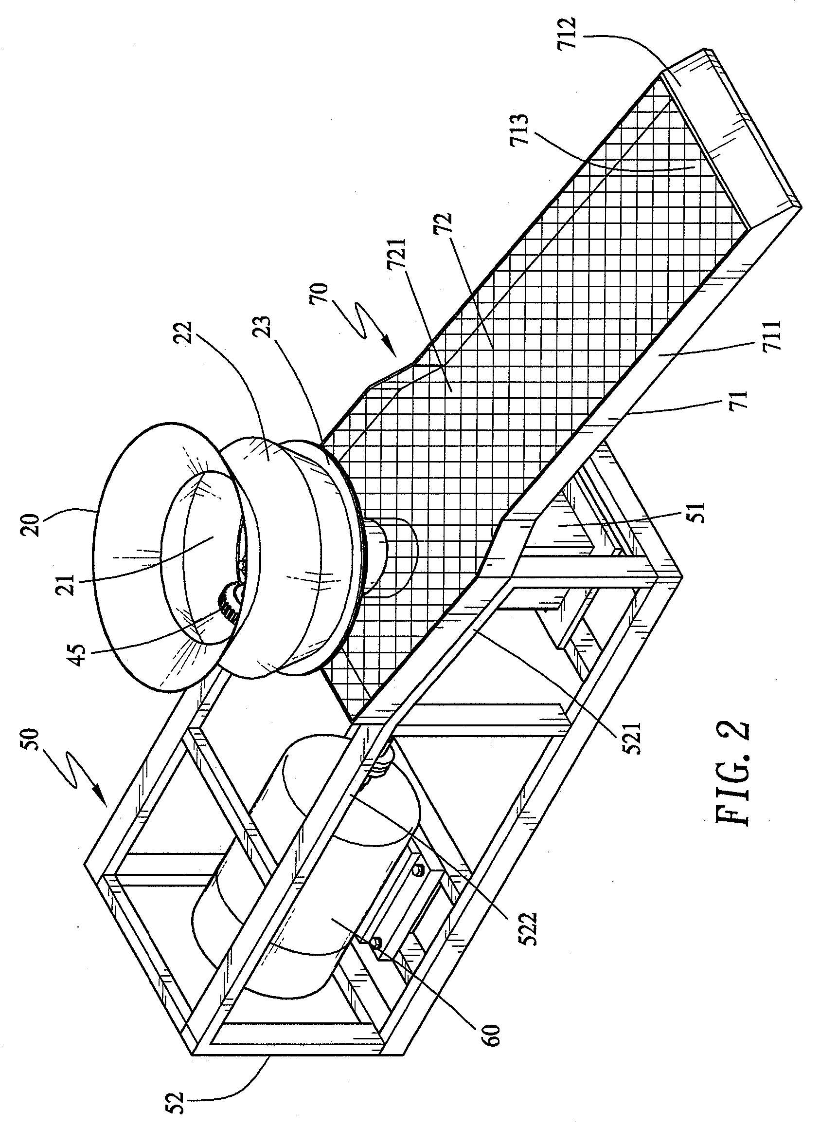
[0030]Please refer to FIGS. 2 and 3 that are perspective and longitudinal sectional views, respectively, of a plodder machine according to a preferred embodiment of the present invention. As shown, the plodder machine includes a raw material receiving member 20, a forming member 30, a rolling device 40, a mounting base 50, a power transmission device 60, and a screening discharging device 70. The forming member 30 is externally mounted to a bottom of the raw material receiving member 20 to together define a receiving space 21 for receiving a raw material to be formed into a specific shape. The rolling device 40 is mounted on the forming member 30 to locate in the receiving space 21 at a bottom thereof. A vertical driving shaft 41 is connected to a bottom of the rolling device 40 and meshed with a horizontal driving shaft 61 of the power transmission device 60. The mounting base 50 is connected to a bottom of the forming member 30 via fastening elements. The power transmission device...


PUM

PropertyMeasurementUnit
temperatureaaaaaaaaaa
diameteraaaaaaaaaa
sizesaaaaaaaaaa

Abstract

A plodder machine includes a raw material receiving member, a forming member mounted to a bottom of the receiving member to define a receiving space therebetween, a rolling device mounted in the receiving space, and a mounting base supporting the forming member and a power transmission device thereon. The rolling device is driven by the power transmission device to rotate horizontally and thereby press a raw material into a plurality of forming holes circularly arrayed on the forming member to form bar-shaped products. A screening discharging device is connected to the mounting base and located below the forming member to catch and separate the bar-shaped products from recyclable raw material fragments at reduced labor and time costs. Forming sleeves each having a bore of different cross sectional shape and size can be selectively fitted in the forming holes to change the cross-sectional shapes and sizes of the bar-shaped products.

Description

FIELD OF THE INVENTION[0001]The present invention relates to a plodder machine for forming bar-shaped environment-friendly charcoal products, and more particularly to a plodder machine that provides upgraded bar forming efficiency and bar-shaped products of various cross sectional shapes and sizes, and automatically collects and separates recyclable raw material fragments from the bar-shaped products to save time and labor costs for subsequent removal of raw material fragments from the products.BACKGROUND OF THE INVENTION[0002]The environment-friendly charcoal is a substitute for the conventional charcoal, and the main raw materials thereof include agricultural wastes rich in botanical fibers, such as straws, wood dust, corn stalks, etc. To manufacture the environment-friendly charcoal, first grind and evenly mix the raw materials and then heat the mixed raw materials. Finally, the heated raw material mixture is compressed using a plodder machine into a desired shape for consumers t...

Claims


Application Information

Patent Timeline
Patent Type & Authority Applications(United States)
IPC IPC(8): B29C47/10B29C48/06B29C48/12B29C48/285B29C48/355
CPCB29C47/0016B29C47/003B29C47/0801B29C47/1027B29C47/34B29C47/54B29C47/1009B29C47/10B29C48/288B29C48/06B29C48/12B29C48/252B29C48/285B29C48/286B29C48/355
Inventor LAI, KUEI-TSAI
Owner LAI KUEI TSAI
Why Eureka
Eureka Blog
Learn More