
Low-cost switch sensor remote dead bolt status indicator

a status indicator and switch sensor technology, applied in the direction of testing/monitoring control systems, program control, instruments, etc., to achieve the effects of low power consumption, extended battery life, and extended life of transmitter sub-assembly batteries

Inactive Publication Date: 2010-12-16
EICHENSTEIN JOSEPH
View PDF11 Cites 31 Cited by
  • Summary
  • Abstract
  • Description
  • Claims
  • Application Information

AI Technical Summary

Benefits of technology

[0010]It is an object of the present invention to provide a low-cost switch sensor remote dead bolt status indicator.
[0012]It is also an object of the present invention to provide a low cost remote door lock indicator with a self shut-off feature operating after a fixed duration of time length has elapsed.
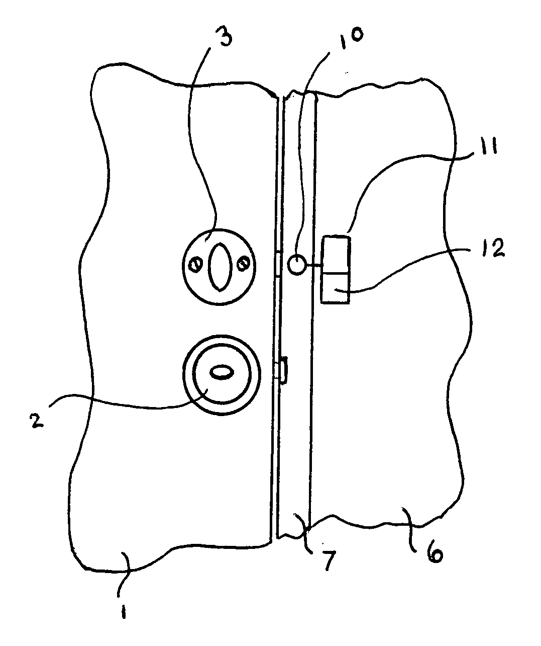
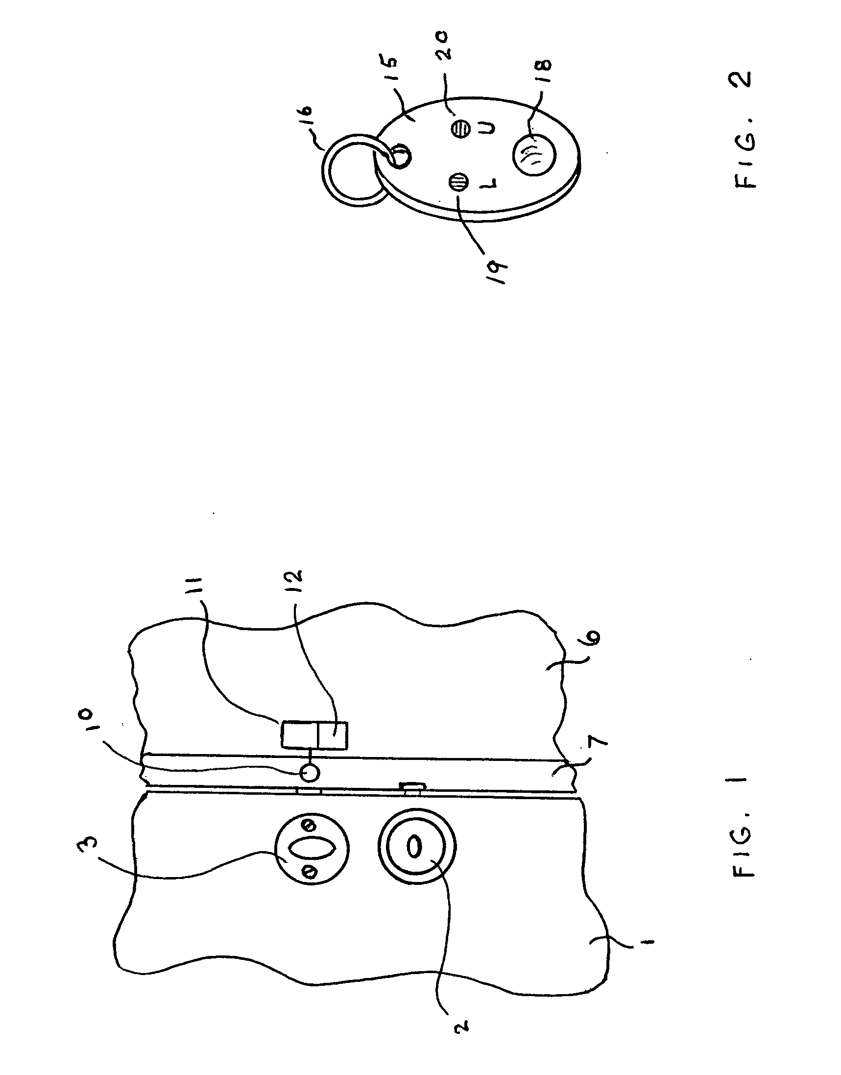
[0015]In keeping with these objects and others which may become apparent, this invention is a low-cost system using a transmitter unit comprising a transmitter and a switch sensor to detect the presence of a dead bolt in a locked position, whereby the door to secured is assuredly locked / secured. The switch sensor is dual purpose. It is used to start the transmitter operation as well as to sense the bolt position in a very direct manner. The transmitter is low voltage or battery operated, such as, for example, using ordinary alkaline batteries (such as 2 or 3 AA cells). This type of power for powering the transmitter unit avoids the first cost of an AC line-powered power supply or charging stand; an ugly extension cord is also avoided in this manner. Please note, however, that an alternative embodiment includes AC / DC converter connected to power the switch sensor, transmitter and any logical circuitry for application where changing a battery would be inconvenient. A very small hand-held indicator, such as a key fob powered by a button cell, contains a receiver to communicate with the transmitter at the door.
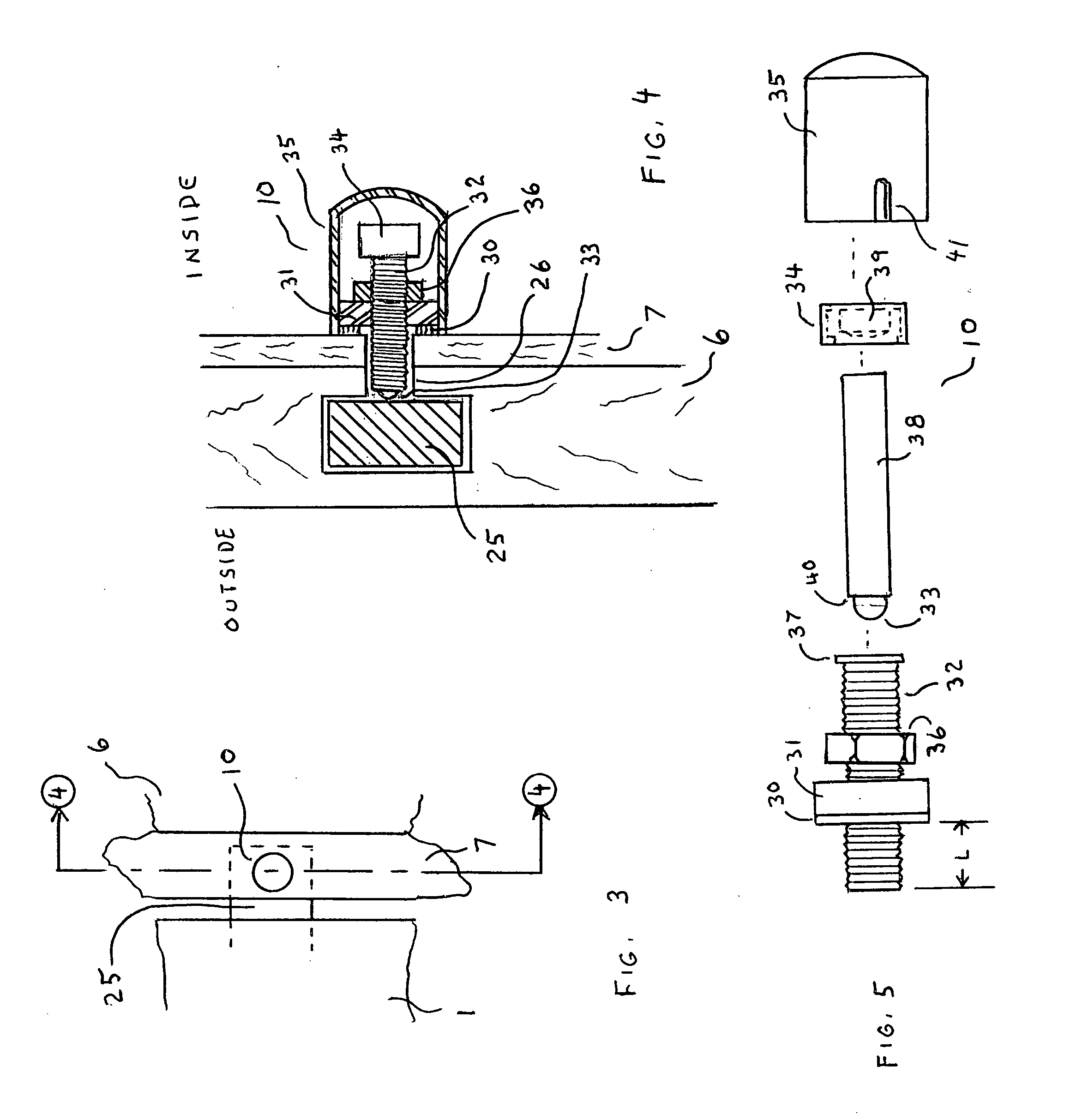
[0016]A major feature of this invention is the ease of installation of the transmitter unit at the door with the switch sensor by a customer with average skills and minimal tools. In fact, the only tool necessary is a drill capable of drilling a single hole adjacent the dead bolt. Beyond low first cost, low cost operation in terms of long battery life is also a feature of this invention.
[0024]To greatly extend the life of the transmitter subassembly battery, the signal transmission is preferably pulse modulated with full power pulses of a reduced nature, such as, for example, only a 5% duty cycle or less, for example, pulses of radio frequency of 5 ms duration every 100 ms period. In this manner, full range is not sacrificed since the pulses are full power, but the battery life is extended over ten-fold compared to continuous full power transmission over the five minute transmission periods. The service life of the key fob receiver battery is very long since the receiver and indicator LED's are only operated while the inquiry button is pressed. Besides, a receiver function is a low power device compared to the transmitter function of a normal remote keyless entry automotive fob. The key fob unit is configured for easy replacement of the battery cell therein.
[0025]In an alternate embodiment, the switch sensor is provided as an integral part bonded to the conventional manufactured metal strike plate dead bolt frame that is typically attached to the door jamb. The switch sensor may be attached to the metal strike plate by two fingers extending rearward from the strike plate, or by any other mounting means which mounts the sensor to the strike plate in the vicinity of where the dead bolt moves to during the locking operation. The important feature is that the dead bolt, upon locking, is introduced through the cowling of the access hole of the strike plate in a locked position, where it activates the switch sensor concealed within an access hole for the deadbolt. The switch sensor generates a signal to activate the transmitter assembly communicating with the user's key fob, i.e., the receiver thereat. The switch sensor is preferably therefore concealed within the access hole for the dead bolt. It is a very low profile, dome operated switch, requiring only a small hole through to the interior for a small gage two-conductor cable to the transmitter assembly. This alternate embodiment simplifies the installation of the security system. Costs are minimal in view of the fact that the door jamb strike plate may be manufactured with the switch sensor by a dead bolt lock manufacturer.

Problems solved by technology

However, the prior art does not reveal a remote dead bolt status indicator which is low cost and uses a switch sensor easily installed by the customer.

Method used


Image

  • Low-cost switch sensor remote dead bolt status indicator
  • Low-cost switch sensor remote dead bolt status indicator
  • Low-cost switch sensor remote dead bolt status indicator

Examples


Embodiment Construction

[0036]The following is a detailed description of example embodiments of the invention depicted in the accompanying drawings. The example embodiments are in such detail as to clearly communicate the invention. However, the amount of detail offered is not intended to limit the anticipated variations of embodiments; on the contrary, the intention is to cover all modifications, equivalents, and alternatives falling within the spirit and scope of the present invention, as defined by the appended claims. The descriptions below are designed to make such embodiments obvious to a person of ordinary skill in the art.

[0037]A low-cost switch sensor remote dead bolt status indicator includes a switch sensor which starts a transmitter at a door lock location upon sensing of a dead bolt being in a locked position. The transmitter is provided with a self shut-off feature operating after a fixed duration of minutes length has elapsed. The indicator also includes a receiver in a hand held unit, such ...


PUM


Abstract

A low-cost switch sensor remote dead bolt status indicator includes a switch sensor which starts a transmitter at a door lock location upon sensing of a dead bolt entering into a locked position. The transmitter is provided with a self shut-off feature operating after a fixed duration of minutes length has elapsed. The indicator also includes a receiver in a hand held unit, such as a key fob capable of receiving signals from the transmitter after the user presses an inquiry key on its surface. The hand held receiver having two indicators for alternately displaying the lock's dead bolt status as being locked or unlocked. In an alternate embodiment, the switch sensor is provided as an integral part bonded to the conventional manufactured metal strike plate dead bolt frame that is typically attached to the door jamb.

Description

FIELD OF THE INVENTION[0001]The present invention relates to low cost remote reminders whether a dead bolt lock of a building door is locked or unlocked.BACKGROUND OF THE INVENTION[0002]People often leave their house and wonder whether they locked the dead bolt of their front door. Typically they would have to get out of their car and return to the house and check to see if the door is bolted. While remote status checking devices using radio communications links are known, a simple low cost device is needed.[0003]US Patent application 2004 / 0080403 of Eshel relates to a lock status indicator. It comprises a remote indicator in the form of a key fob that has a visual or audio indication of the status of a vehicle lock. A time indicating device may also display the time of the last lock status change. No information on the communication sequence or operation of the indicator is provided by the inventor.[0004]U.S. Pat. No. 6,703,919 of Baset describes a method of confirming remote keyle...

Claims


Application Information

Patent Timeline
IPC IPC(8): E05B41/00E05B65/06E05B17/00G05B19/00
CPCE05B15/0205E05B41/00E05B2047/0069E05B2047/0094Y10T70/5296Y10T70/8027Y10T70/80
Inventor EICHENSTEIN, JOSEPHMIZZI, JOHN V.
Owner EICHENSTEIN JOSEPH
Learn More