Heat exchanger

a technology of heat exchanger and heat exchange medium, which is applied in the direction of refrigerating machines, lighting and heating apparatus, fluid circulation arrangement, etc., can solve the problems of non-uniform distribution of refrigerant into the plurality of heat exchange tubes, inconvenient use, and insufficient parts, etc., to achieve uniform distribution reduce separation of heat exchange medium, and simple construction

Inactive Publication Date: 2010-12-16
GLOSTER
View PDF9 Cites 19 Cited by
  • Summary
  • Abstract
  • Description
  • Claims
  • Application Information

AI Technical Summary

Benefits of technology

[0008]According to this heat exchanger, at least part of the (existing, in-flowed) heat exchange medium that has already flowed into the entrance header (i.e., heat exchange medium already present inside the entrance header) is sprayed in the axial direction of the circulating conduit by the pressure difference generating mechanism and forcibly circulated inside the circulating conduit which is fluidly connected to the plurality of tubes. This means that the state of the heat exchange medium inside the circulating conduit of the input header can be made more uniform or close to uniform. For example, even when a two-phase heat exchange medium including a gas phase and a liquid phase has flowed into the header, it is possible to suppress separation of the heat exchange medium into a liquid phase component and a gas phase component inside the entrance header. This means that even if the entrance header is fairly long in the axial direction and a plurality of tubes are fluidly connected so as to be distributed in the axial direction of the entrance header, it will still be possible to distribute the heat exchange medium to the respective tubes in a more uniform state.
[0009]According to this heat exchanger, it may omit distributor having pipes bent in complex three dimensions. It may also omit machining that bends tubes complexly to make the distribution of the heat exchange medium more uniform. Note that the present heat exchanger does not exclude devices that have pipes and tubes laid out in three dimensions or bent by machining in three dimensions. According to the present heat exchanger, it is possible to make the phase state and amount of the heat exchange medium distributed to the tubes uniform or close to uniform using a simpler construction. This means that a heat exchanger with favorable heat exchanging efficiency can be provided at comparatively low cost.
[0010]One example of a pressure difference generating mechanism is driven by an external force such as a pump. In a cooling system or the like, the heat exchange medium that flows into the heat exchanger is reduced in pressure or expanded in advance. For a heat exchanger used in such a system, it is possible to drive the pressure difference generating mechanism using the energy of the heat exchange medium. Here, since a new driving source is not required aside from a driving source typically used in a heat exchanger, the heat exchanger is economical. That is, the pressure difference generating mechanism should preferably be driven by the heat exchange medium flowing into the entrance header. As the pressure difference generating mechanism, it is possible to use a construction such as a supercharger (a construction that resembles a supercharger) that rotates a turbine using the pressure of a driving part and forcibly draws in the heat exchange medium using a pressure difference generating part (a pressurizing part) such as a coaxial compressor.

Problems solved by technology

This means that inside the header, the liquid phase component whose specific gravity is higher and is susceptible to the effect of gravity and the gas phase component whose specific gravity is lower and is less susceptible to the effect of gravity tend to separate, resulting in the distribution of refrigerant into the plurality of heat exchange tubes becoming non-uniform.
This non-uniformity in the distribution of the heat exchange medium is especially noticeable when a heat exchanger is used in a posture where the header is vertical.
This means that more parts are needed and the manufacturing cost tends to be higher.
In addition, since space is required to dispose the distribution tubes that are bent in three dimensions, there tends to be an increase in the size of the header and the heat exchanger.
With this construction, the state of the refrigerant at the entry to the plurality of flat distribution tubes is close to uniform, but since there are differences in the pressure drop between tubes due to differences in the lengths of the tubes, the distribution of refrigerant to the plurality of tubes will not necessarily become uniform.
In addition, since a plurality of flat distribution tubes with curved parts are disposed in this construction, a heat exchanger with a simple construction cannot be provided.
However, even if spray orifices are provided at the entrance to the entrance header as in the evaporator disclosed in this document, it will still be difficult to spray the refrigerant uniformly into the entire header, with the sprayed amount and distribution tending to be affected by the flow rate.
It is also difficult to incorporate a construction, which is capable of producing a suitable distribution in accordance with the flow rate by adjusting the layout of the orifices, their orientation, and the protruding amount into the tubes, inside the header.
It is also difficult to obtain a suitable distribution of refrigerant in response to fluctuations in conditions such as rises and falls in the flow rate, the orientation of the header, and the pressure inside the tubes.

Method used


Image

  • Heat exchanger
  • Heat exchanger
  • Heat exchanger

Examples


first embodiment

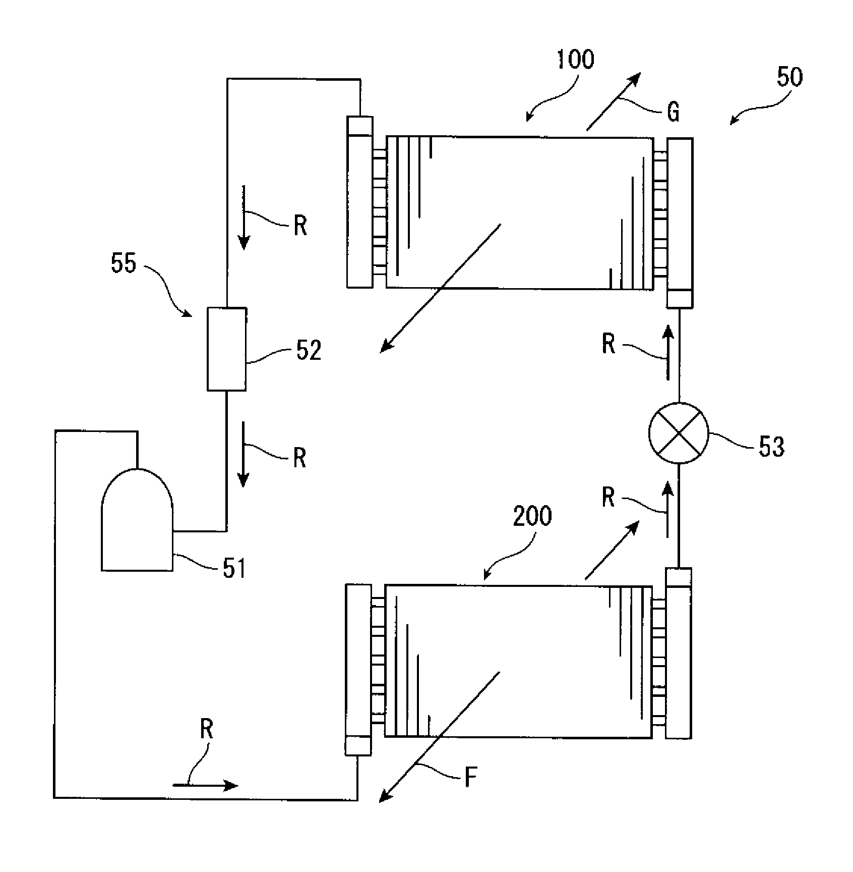
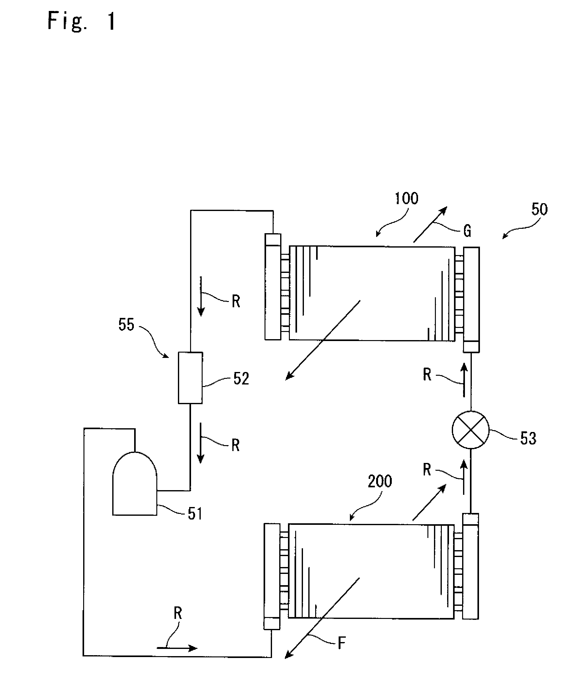
[0028]FIG. 2 shows a heat exchanger 100a according to the present invention. This heat exchanger 100a can be used as the evaporator 100 of the system 50. The heat exchanger 100a includes an entrance header 1 that includes a refrigerant inlet 6, an exit header 2 that includes a refrigerant outlet 5, and a heat exchanging part 20. The entrance header 1 and the exit header 2 both extend in the up-down direction (vertical direction) and are disposed so as to be parallel to one another. The heat exchanging part 20 exchanges heat between the refrigerant R and the air G or the like so as to cool the air G or the like. The heat exchanging part 20 includes a plurality of tubes 4, which are disposed in parallel in the horizontal direction so as to fluidly connect the entrance header 1 and the exit header 2, and fins 3, which extend in the up-down direction so as to be perpendicular to the tubes 4.

[0029]A typical example of the tubes 4 are tubes that are circular in cross-section, but the tube...

second embodiment

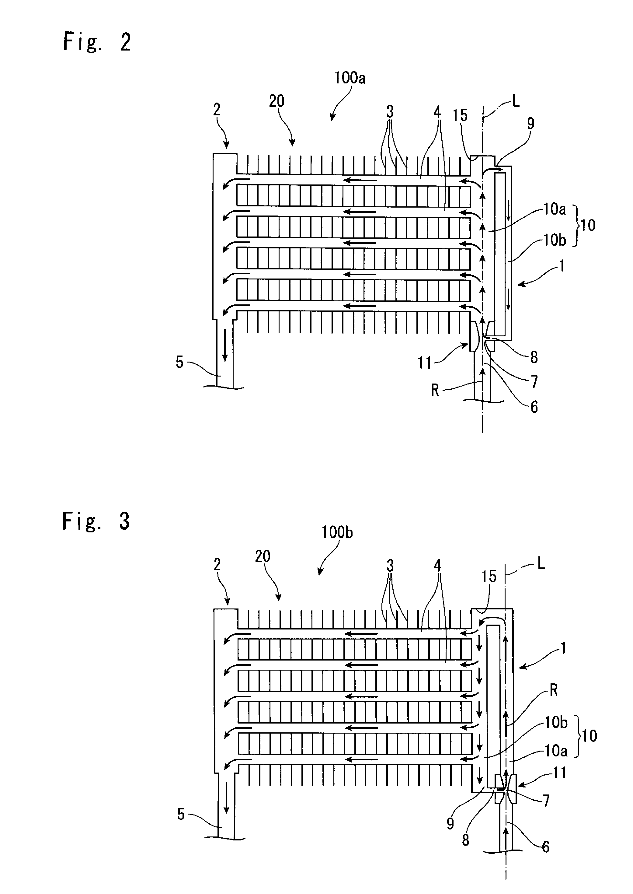
[0038]FIG. 3 shows a heat exchanger 100b according to the present invention. This heat exchanger 100b can also be used as the evaporator 100 of the heat exchange system 50 described above. In the heat exchanger 100b, a plurality of tubes 4 are connected at substantially equal intervals to the return channel 10b of the circulating conduit 10 of the entrance header 1. In the circulating conduit 10 in which at least part of the in-flowed refrigerant R is forcibly circulated, the state of the refrigerant R becomes substantially uniformly mixed phase in not only the outward channel 10a but also the return channel 10b. Accordingly, it is possible to distribute the refrigerant R substantially uniformly to the respective tubes 4 when the tubes 4 are fluidly connected to the return channel 10b. In addition, at a position that is somewhat distant from the throat part 7, for example, at the return channel 10b, the phase state of the refrigerant R mixed by suction tends to be more stable or uni...

third embodiment

[0039]FIG. 4 shows a heat exchanger 100c according to the present invention. This heat exchanger 100c can also be used as the evaporator 100 of the heat exchange system 50 described above. In the heat exchanger 100c, the entrance header 1 includes a U-shaped tube that includes two straight parts, with such straight parts being fluidly connected at the open end of the U shape by the drawing channel 9. The entrance header 1 includes a circulating conduit (circulating pathway) 10 and both the outward channel 10a and the return channel 10b of the circulating conduit 10 are fluidly connected to the plurality of tubes 4. Accordingly, it is possible to supply the refrigerant R in a substantially uniform state to the plurality of tubes 4 that are aligned in two columns along the outward channel 10a and the return channel 10b. According to the heat exchanger 100c, it is possible to further increase the heat exchange efficiency of the heat exchanging part 20 without changing the surface area ...


PUM


Abstract

A heat exchanger (100a) includes a plurality of tubes (4), an entrance header (1) for distributing a refrigerant to the tubes (4), and an exit header (2) for collecting the refrigerant from the tubes (4). The entrance header (1) includes a circulating conduit (10) capable of circulating at least part of the refrigerant that has flowed into the entrance header (1), and the plurality of tubes (4) are fluidly connected to the outward channel (10a) of the circulating conduit (10). The entrance header (1) also includes an ejector 11 that uses the refrigerant flowing into the entrance header to draw and mix at least part of the refrigerant that has flowed into the entrance header and spray out the mixed refrigerant. The entrance header (1) can supply refrigerant more uniformly to the tubes (4) connected to the circulating conduit (10).

Description

TECHNICAL FIELD[0001]The present invention relates to a heat exchanger used in a freezer, refrigerator, or the like.BACKGROUND ART[0002]In a heat exchanger, to increase the heat exchange efficiency, it is important to distribute a heat exchange medium that has been supplied to a header uniformly to a plurality of heat exchange tubes. However, in a heat exchanger or in particular, in an evaporator, it is normal for the heat exchange medium (refrigerant) to be in a two-phase state including a gas phase and a liquid phase. This means that inside the header, the liquid phase component whose specific gravity is higher and is susceptible to the effect of gravity and the gas phase component whose specific gravity is lower and is less susceptible to the effect of gravity tend to separate, resulting in the distribution of refrigerant into the plurality of heat exchange tubes becoming non-uniform. This non-uniformity in the distribution of the heat exchange medium is especially noticeable whe...

Claims


Application Information

Patent Timeline
Patent Type & Authority Applications(United States)
IPC IPC(8): F28F9/02
CPCF25B39/028F25B41/00F25B2341/0011
Inventor MORIYA, TORUMAEZAWA, TAKAHIDENAKABOU, TADASHI
Owner GLOSTER
Why Eureka
Try Eureka