Tag antenna using microstrip line, method of manufacturing the same and radio frequency identification tag

a microstrip line and antenna technology, applied in the direction of resonant antennas, radiating element structural forms, instruments, etc., can solve the problems of miniaturization and cost disadvantages, and achieve the effect of effective impedance matching, small resistance components, and large capacitive reactan

Inactive Publication Date: 2010-12-16
ELECTRONICS & TELECOMM RES INST +1
View PDF11 Cites 22 Cited by
  • Summary
  • Abstract
  • Description
  • Claims
  • Application Information

AI Technical Summary

Benefits of technology

[0010]Accordingly, in one aspect, there is provided a tag antenna capable of effectively achieving an impedance matching wit

Problems solved by technology

However, since the power transfer of the RFID reader is subject to local regulations of the relevant country in addition to the federal communication commission (FCC) of the USA, the increase of power trans

Method used


Image

  • Tag antenna using microstrip line, method of manufacturing the same and radio frequency identification tag
  • Tag antenna using microstrip line, method of manufacturing the same and radio frequency identification tag
  • Tag antenna using microstrip line, method of manufacturing the same and radio frequency identification tag

Examples


Embodiment Construction

[0028]The following detailed description is provided to assist the reader in gaining a comprehensive understanding of the methods, apparatuses and / or systems described herein. Various changes, modifications, and equivalents of the systems, apparatuses and / or methods described herein will suggest themselves to those of ordinary skill in the art. Descriptions of well-known functions and structures are omitted to enhance clarity and conciseness.

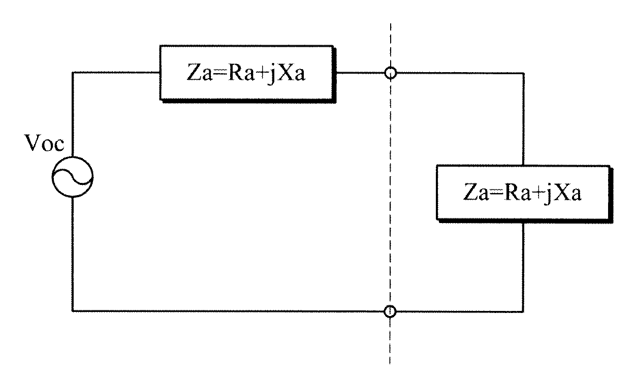
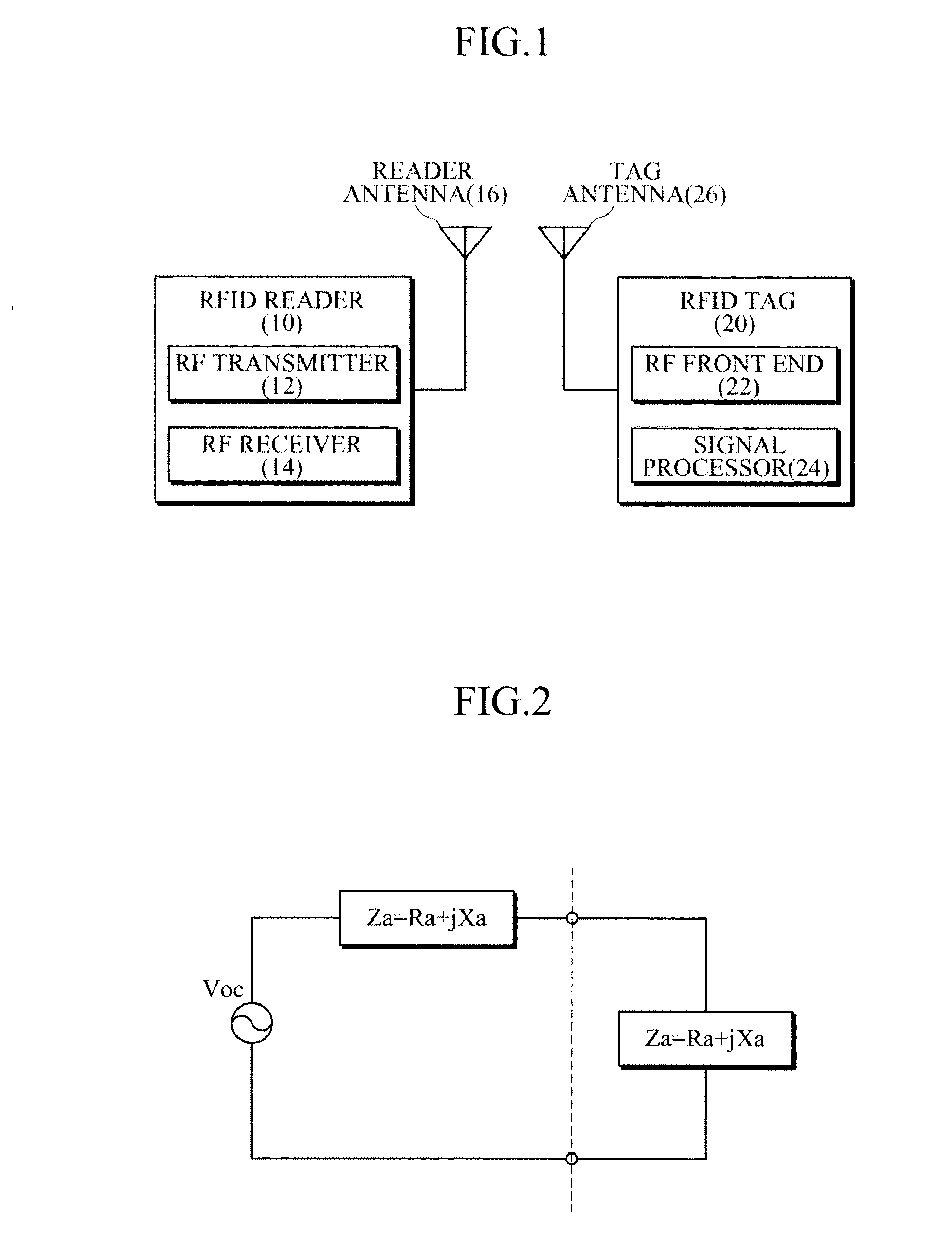
[0029]FIG. 1 is a block diagram of an exemplary RFID system. As shown in FIG. 1, a radio frequency identification (RFID) system includes a RFID tag 20, an RFID reader 10 capable of reading and decoding data of the RFID tag and a host computer for processing data read by the RFID tag 20.

[0030]The RFID reader 10 includes an RF transmitter 12, an RF receiver 14 and a reader antenna 16. The reader antenna 16 is electrically connected to the RF transmitter 12 and the RF receiver 14. The RFID reader 10 transmits an RF signal to the RFID tag 20 through...


PUM


Abstract

Disclosed is a Radio Frequency Identification (RFID) tag antenna. The tag antenna includes a lower dielectric substrate and an upper dielectric substrate. The lower dielectric substrate is provided at a lower surface thereof with a ground plane and at an upper surface thereof with two microstrip lines. The microstrip lines each have an open-end, the open ends spaced apart from each other from a middle of the lower dielectric substrate while facing each other to form a radiating slot from which radiation of electromagnetic waves occurs. The upper dielectric substrate is provided at an upper surface thereof with at least one electric capacitive device and is stacked on the lower dielectric substrate. The RFID tag antenna enhances radiation efficiency while achieving miniaturization.

Description

CROSS-REFERENCE TO RELATED APPLICATION[0001]This application claims the benefit under 35 U.S.C. §119(a) of Korean Patent Application No. 10-2009-0053591, filed on Jun. 16, 2009, the disclosure of which is incorporated by reference in its entirety for all purposes.BACKGROUND[0002]1. Field[0003]The following description relates to an antenna and a Radio Frequency Identification (RFID) tag.[0004]2. Description of the Related Art[0005]A radio frequency identification (RFID) tag is used in cooperation with a radio frequency identification (RFID) reader in various fields including materials management, security and so on. In general, if an object to which an RFID tag is attached is placed within a read zone of a RFID reader, the RFID reader modulates an RF signal having a predetermined carrier frequency and transmits an interrogation signal to the RFID tag. The RFID tag responses to the interrogation signal of the RFID reader.[0006]That is, the RFID reader modulates continuous electromagn...

Claims


Application Information

Patent Timeline
IPC IPC(8): G06K19/00H01Q1/38
CPCG06K19/07786H01Q1/2208H01Q13/103H01Q1/38H01Q1/24G06K19/077
Inventor KIM, JEONG-SEOKSON, HAE-WONCHOI, WON-KYUCHOI, GIL-YOUNGCHAE, JONG-SUK
Owner ELECTRONICS & TELECOMM RES INST
Why Eureka
Try Eureka