Structure of radio frequency variable capacitor and method of manufacturing the same

Inactive Publication Date: 2005-03-08
SAMSUNG ELECTRONICS CO LTD
View PDF6 Cites 0 Cited by
  • Summary
  • Abstract
  • Description
  • Claims
  • Application Information

AI Technical Summary

Benefits of technology

The present invention provides a structure of a radio frequency (RF) variable capacitor to improve a quality factor while using a CMOS process by reducing an internal parasitic resistance component.

Problems solved by technology

Meanwhile, according to a recent trend in mobile communication systems, an RF IC using a silicon process technology has been developed, and problems that are now being faced in designing the RF IC are proper modeling of a passive element at a frequency bandwidth of several tens of GHz.
In particular, it is difficult to integrate a VCO using a passive element such as an inductor or a variable capacitor.
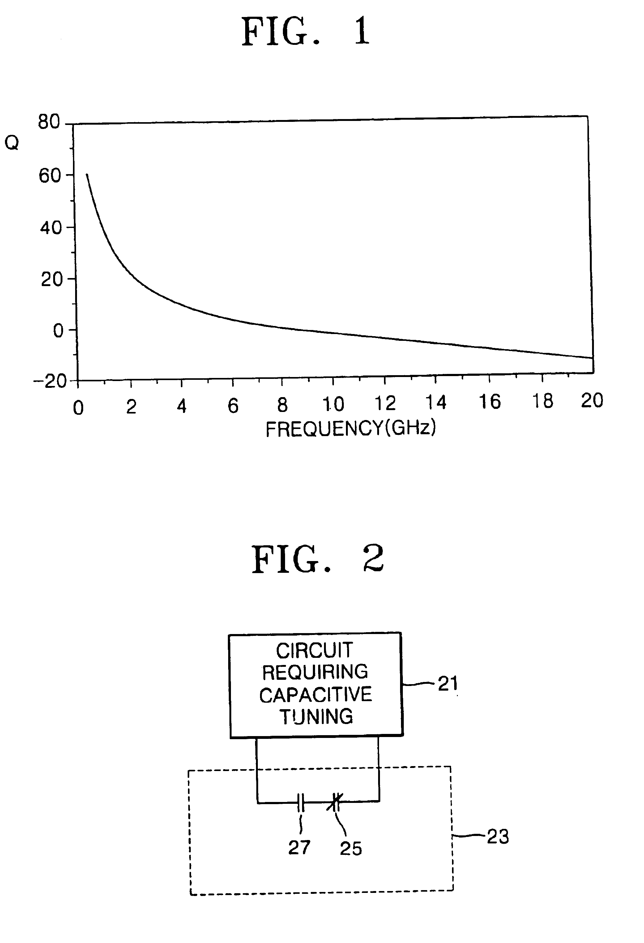
That is, if the passive element is used at an RF bandwidth of several tens of GHz, a quality factor is reduced, and as a frequency increases, losses caused by a coupling effect and a skin effect with a substrate increase.
However, in spite of its advantages, the MEMS variable capacitor has a tuning voltage from at least 5V to several tens of V. Thus, it is very difficult to use the MEMS variable capacitor in an existing low power consumption element, in particular, a low voltage operating system for a CMOS and an RF communication device.
Further, an additional process is required to integrate the MEMS variable capacitor into a CMOS RF IC, thereby increasing costs.

Method used


Image

  • Structure of radio frequency variable capacitor and method of manufacturing the same
  • Structure of radio frequency variable capacitor and method of manufacturing the same
  • Structure of radio frequency variable capacitor and method of manufacturing the same

Examples


Embodiment Construction

Korean Patent Application No. 2002-68574, filed on Nov. 6, 2002, and entitled: “Structure Of Radio Frequency Variable Capacitor And Method Of Manufacturing The Same,” is incorporated by reference herein in its entirety.

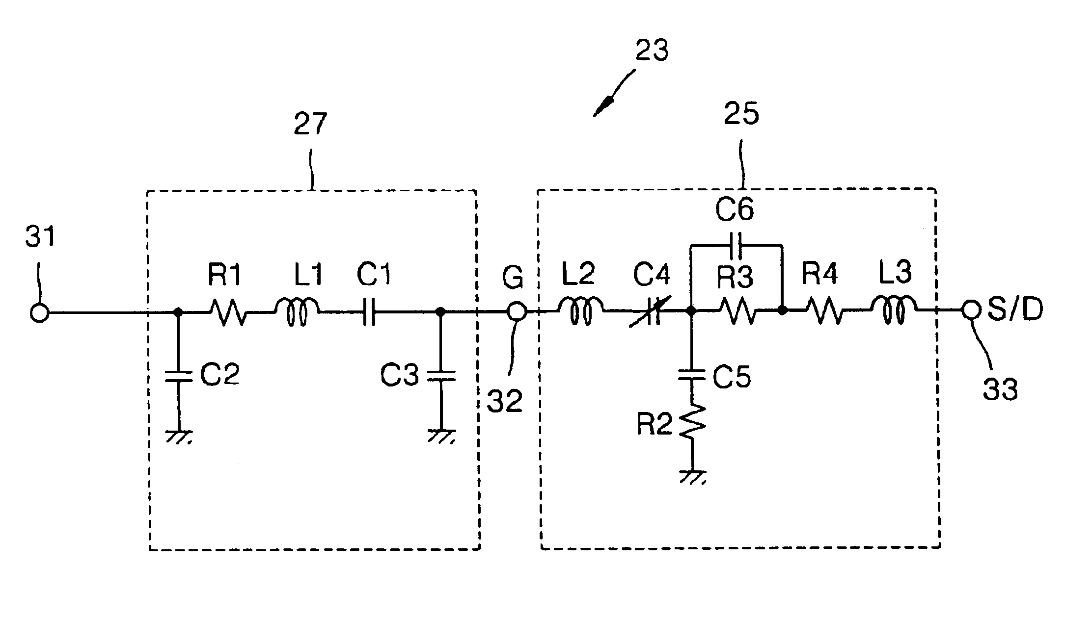
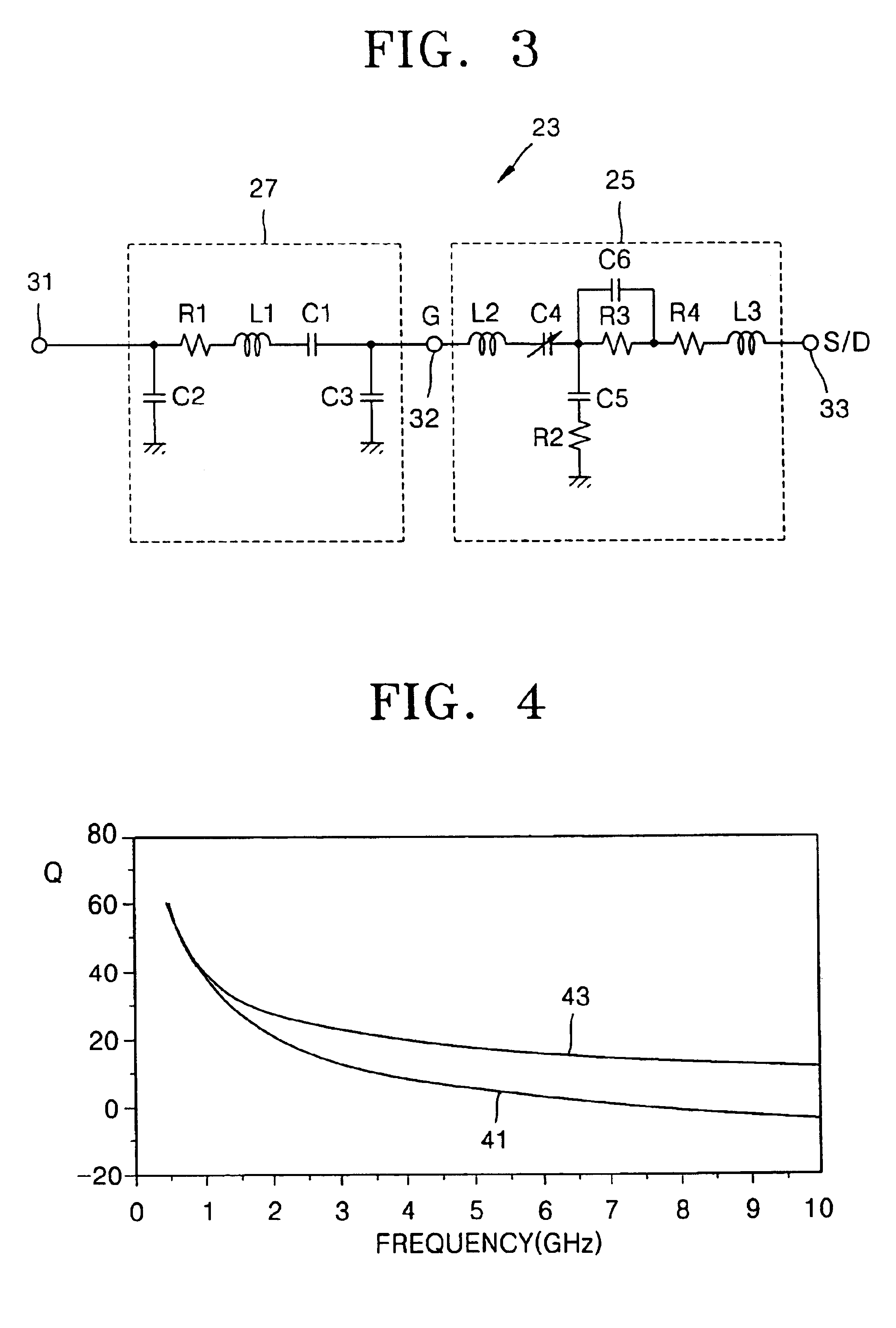
The present invention will now be described more fully hereinafter with reference to the accompanying drawings, in which preferred embodiments of the invention are shown. The invention may, however, be embodied in different forms and should not be construed as limited to the embodiments set forth herein. Rather, these embodiments are provided so that this disclosure will be thorough and complete, and will fully convey the scope of the invention to those skilled in the art. In the drawings, the thickness of layers and regions are exaggerated for clarity. It will also be understood that when a layer is referred to as being “on” another layer or substrate, it can be directly on the other layer or substrate, or intervening layers may also be present. Further, it will be u...


PUM


Abstract

In a structure of a radio frequency (RF) variable capacitor having a variable range of capacitance between a first minimum value and a first maximum value, and a method of manufacturing the structure, the structure includes a first capacitor, which has a variable range of capacitance between a second minimum value greater than the first minimum value and a second maximum value greater than the first maximum value, and a second capacitor, which is connected in series to the first capacitor and has a capacitance of a fixed value. By the structure and method, a quality factor of a radio frequency (RF) variable capacitor may be increased without adding complex processing steps.

Description

BACKGROUND OF THE INVENTION1. Field of the InventionThe present invention relates to a variable capacitor. More particularly, the present invention relates to a structure of a radio frequency variable capacitor to improve a quality factor while using a CMOS process, and a method of manufacturing the same.2. Description of the Related ArtIn a mobile communication system, a radio frequency (RF) block is designed to support many frequency bandwidths. In particular, a variable capacitor having a different capacitance for each frequency bandwidth should be used as a capacitor used in a filter having a direct relation to a frequency bandwidth. In addition, a voltage controlled oscillator (VCO), which is one element in an RF block, adjusts a voltage applied to a variable capacitor to vary the capacitance thereof, and changes a resonance frequency thereby. In this way, the variable capacitor is a very important device for a tunable filter or a VCO for the RF block.Meanwhile, according to a ...

Claims


Application Information

Patent Timeline
IPC IPC(8): H01L27/08H01L29/92
CPCH01L27/0808H01L29/92
Inventor JEON, SANG-YOONSUH, CHUN-DEOK
Owner SAMSUNG ELECTRONICS CO LTD
Why Eureka
Try Eureka