Production of Ultrafine Particles in a Plasma System Having Controlled Pressure Zones
a plasma system and pressure zone technology, applied in the direction of manufacturing tools, silicon oxides, silicon compounds, etc., can solve the problems of disruption of the production process for cleaning equipment, inability to commercialize such processes, and inability to use solid precursors in such processes
- Summary
- Abstract
- Description
- Claims
- Application Information
AI Technical Summary
Benefits of technology
Problems solved by technology
Method used
Image
Examples
example 1
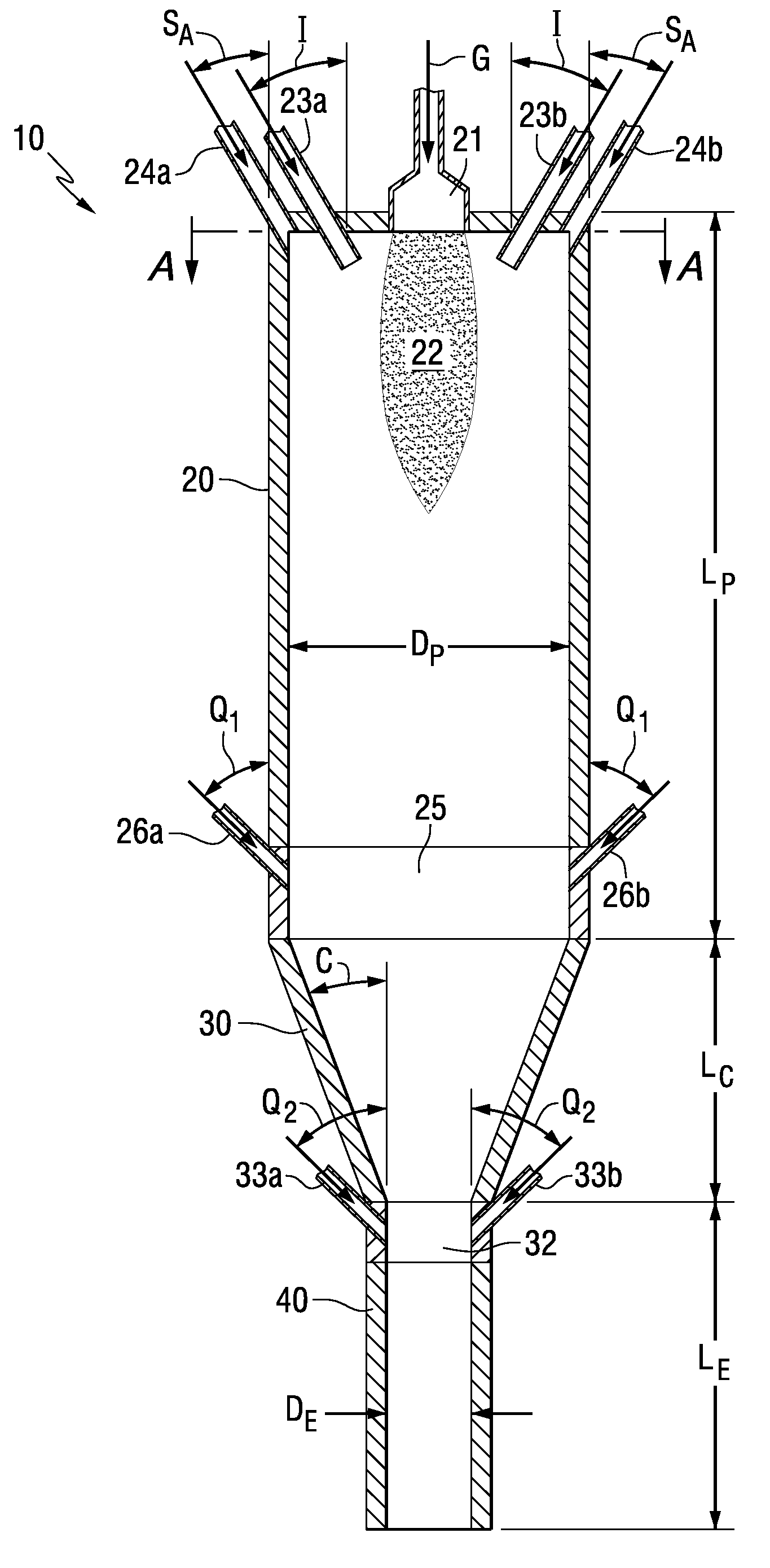
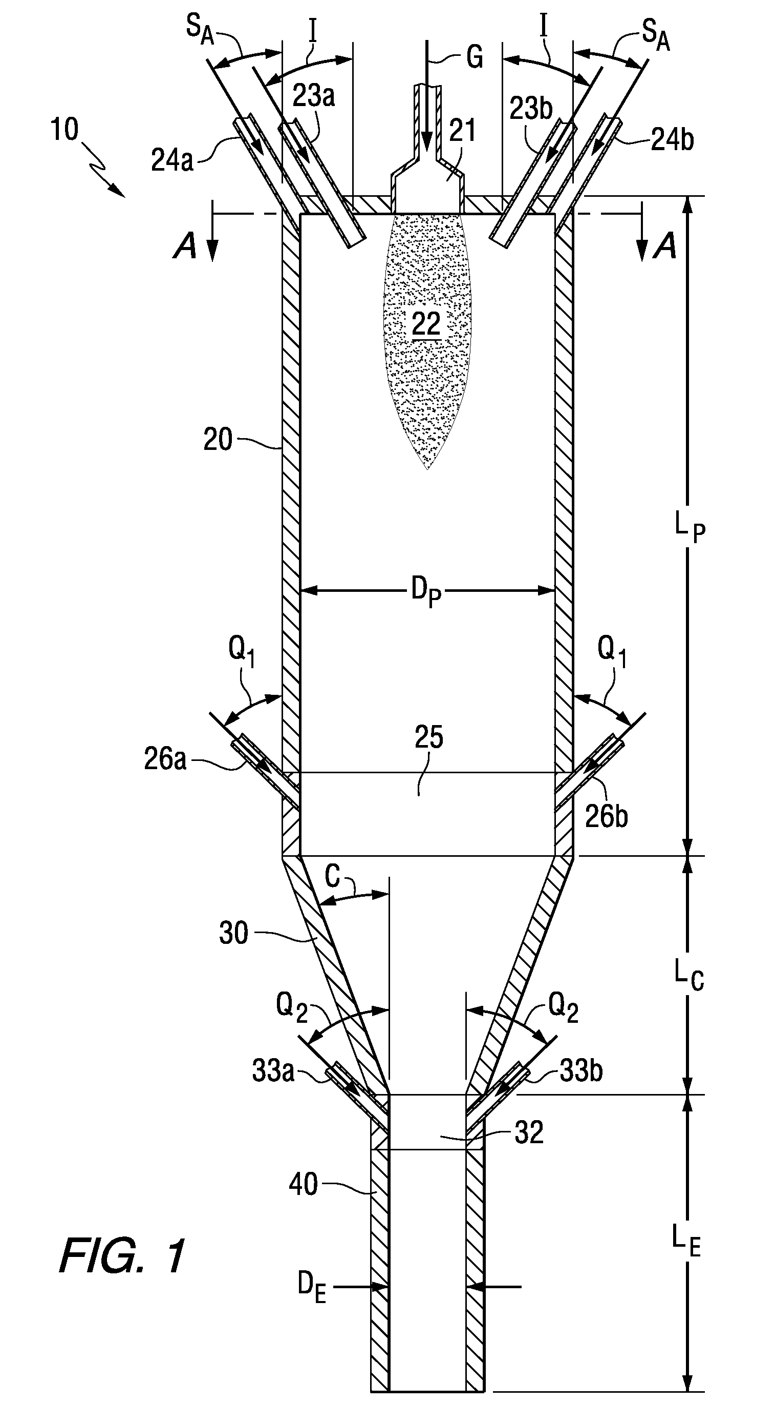
[0055]A computer simulation using commercially available Fluent software was run with a reactor design similar to that shown in FIG. 1 having a 5-foot long cylindrical section, 2.5-foot long conical section, and 3-foot long exit pipe. The diameters of the cylindrical section and the exit pipe are 24 inches ID and 6-inches ID, respectively. The computer simulation is based on several assumed parameters. Plasma air is fed axially through the plasma-gas inlet port which in turn passes through a DC-electric arc that penetrates into the reactor and causes heating. The penetrating arc is approximated to a cylindrical-conical projection into the reactor and modeled via imposing a volumetric energy source in that region. Silica particles carried by air are fed through the two solid feed inlet tubes located on either side of the plasma-gas inlet. Sheath air is fed through four sheath-gas inlets, sized ⅜-inch ID, situated on the cylindrical wall close to the top-plate. The model is created to...
example 2
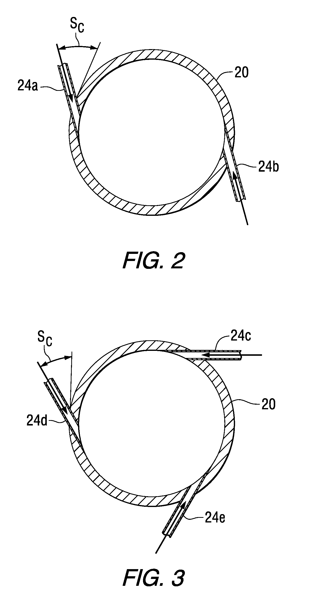
[0059]In a comparative computer simulation, the reactor has the same geometry of Example 1 except the cylindrical section of the reactor has a 16 inch ID. Air at 500 slpm (liter per minute at STP) and 300 K enters the reactor through the main plasma-gas inlet. The plasma arc zone is presumed a cylindrical-conical shaped volume in the model to represent the electric arc penetrating the reactor. A volumetric heat source corresponding to 300 kW is imposed in that region. Also, air at 190 slpm and 300 K is fed through the solid feed inlets. Silica particles are introduced through this inlet at a mass flow rate of 40 lb / hr carried by the air flowing into the reactor. Sheath gas (air) at 1,225 slpm (total for all four sheath gas inlets) is introduced at 300 K. The gas jets enter the reactor swirling in clockwise direction with respect to the reactor axis (x-axis). The swirl is defined by two angles, one at 60° with reactor axis and the other at 30° with the tangent to the reactor circumfe...
example 3
[0061]A reactor was built with the geometry as described in Example 1. Air at 500 slpm was used as plasma gas in a DC plasma torch operated at 300 kW net input to the reactor. Total sheath gas (air) was 198 slpm. Carrier gas (air) at the feed tubes was 82 slpm. Total quench gas (air) at Port #2 was 1,132 slpm. The feed material is solid tungsten oxide powder (Global Tungsten & Powders Corp, Towanda, Pa.) with 16 μm average particle size. The feed rate was controlled at 40 lb / hr. The pressure in the reactor was maintained at 680 torr.
[0062]The measured B.E.T. specific surface area for the produced material was 32 square meters per gram using a Gemini model 2360 analyzer and the calculated equivalent spherical diameter was 26 nanometers.
PUM
| Property | Measurement | Unit |
|---|---|---|
| Fraction | aaaaa | aaaaa |
| Fraction | aaaaa | aaaaa |
| Pressure | aaaaa | aaaaa |
Abstract
Description
Claims
Application Information
 - R&D
- Intellectual Property
- Life Sciences
- Materials
- Tech Scout
- Unparalleled Data Quality
- Higher Quality Content
- 60% Fewer Hallucinations
Browse by: Latest US Patents, China's latest patents, Technical Efficacy Thesaurus, Application Domain, Technology Topic, Popular Technical Reports.
© 2025 PatSnap. All rights reserved.Legal|Privacy policy|Modern Slavery Act Transparency Statement|Sitemap|About US| Contact US: help@patsnap.com


