Flexible pouch and cartridge with fluidic circuits

a fluidic circuit and flexible technology, applied in the field of fluid processing, can solve the problems of large number of sorted cells, large number of fluidic circuits, and relatively complex fluidic circuits, and achieve the effects of high cost, rapid adaptation, and advantageous control of fluid handling

Inactive Publication Date: 2010-12-16
CYNVENIO BIOSYST
View PDF4 Cites 131 Cited by
  • Summary
  • Abstract
  • Description
  • Claims
  • Application Information

AI Technical Summary

Benefits of technology

[0015]Flexible fluid analysis devices, including flexible pouches and flexible cartridges devices, for fluid sample processing, related methods of making and using, related manufacturing systems and related instrumentation systems are described. Flexible pouches provide broad advantage in a wide variety of fields by overcoming the need for complex instrumentation, dedicated devices, and relatively high cost in conventional fluid sample devices. Flexible cartridge devices are particularly advantageous in control of fluid handling, rapid adaptation to a number of configurations by the end user, multiple uses for a single configuration, and in cost and ease of manufacture.

Problems solved by technology

Fluid sample processing devices controlling flow generally involve fairly complex fluidic circuits, dedicated devices and associated instrumentation.
Flow cytometry, however, is relatively complex, requires expensive instrumentation and skilled personnel, and nevertheless requires relatively long times to obtain large numbers (millions) of sorted cells.
For cartridge producers, this requires a relatively high capital cost and skilled personnel.
Even larger systems, for example conventional magnetic bead separation columns, are made of rigid materials and are not adaptable to various configurations using a single cartridge.
Moreover, there are manufacturing constraints in configuration.
Although these devices represent an advance, there are drawbacks.
There is no ability to adapt the column to multiple uses, there is a single inlet and a single outlet, no fluidic circuitry is available.
So, although useful, these columns have limitations.
Regardless, the current technology requires sunk costs, skilled personnel, and dedicated tooling and fixtured devices that are difficult to reconfigure after initial manufacturing.
Moreover, high throughput applications, such as processing large numbers of samples, necessarily are limited by automation adapted for a rigid cartridge (as in the case of the microfluidic devices).

Method used


Image

  • Flexible pouch and cartridge with fluidic circuits
  • Flexible pouch and cartridge with fluidic circuits
  • Flexible pouch and cartridge with fluidic circuits

Examples


embodiments

[0176]In accord with the description herein, one embodiment is a flexible pouch device including a fluidic circuit, the fluidic circuit optionally adapted for microfluidic flow. In one embodiment, the fluidic circuit includes a plurality of reservoirs fluidically connected. In another embodiment, the flexible pouch includes at least one fluidic circuit including at least one reservoir in fluid communication with another reservoir. Embodiments include the flexible pouch device as described and instrumentation providing tensile pressure to effectuate fluidic movement within the flexible pouch.

[0177]Another embodiment is a process for producing a plurality of the flexible pouch devices as described above where the plurality is manufactured on (or from) one or more sheets of polymeric material. One embodiment is a process for manufacturing a plurality of flexible pouch devices from one or more sheets of polymeric material, the method including: (i) arranging the one or more sheets of po...

example 1

Manufacture of Microfluidic Pouch

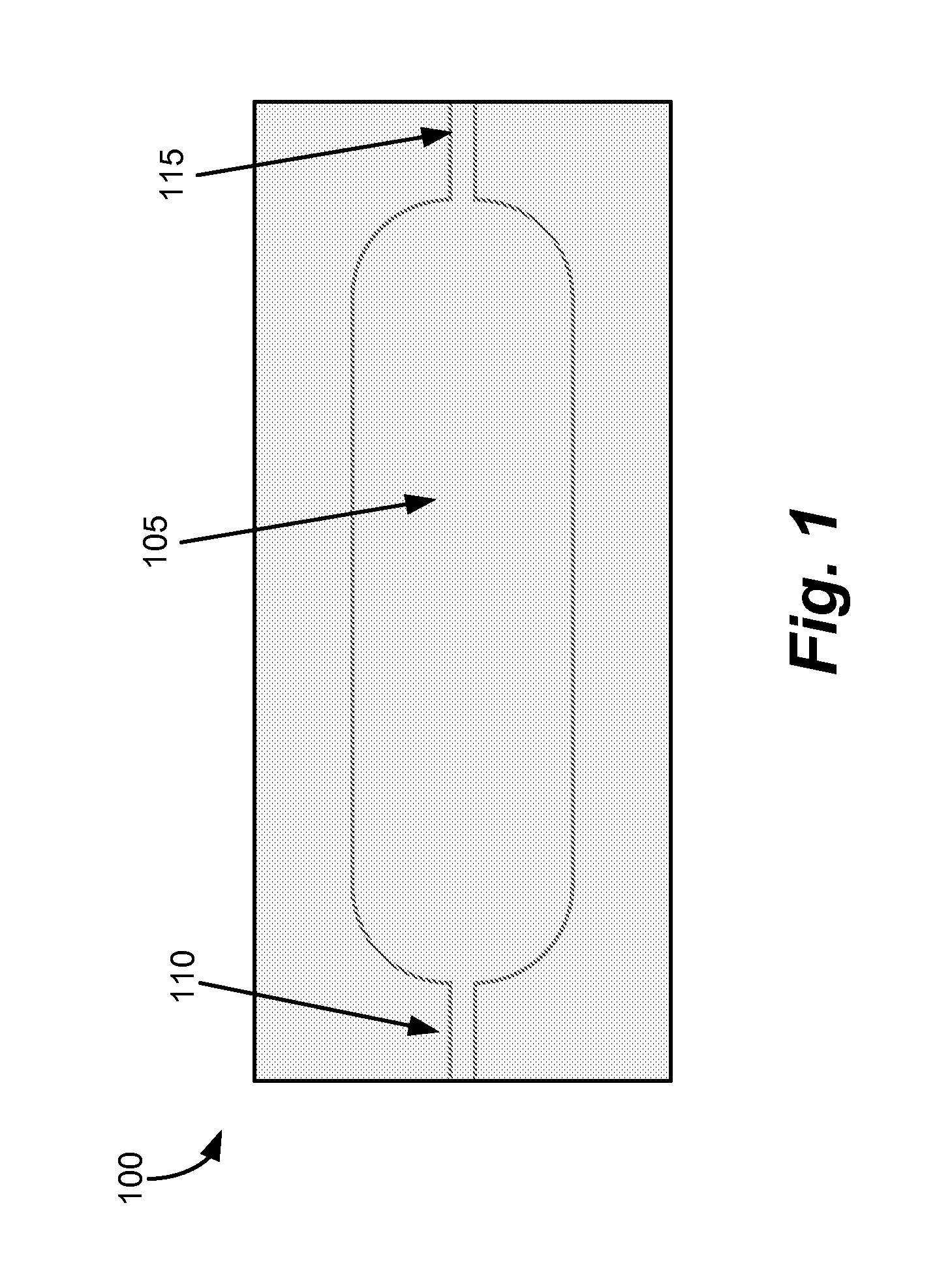
[0191]Pouch Prototype: The prototype of the pouch was produced from 4 mil polyethylene bag (commercial product, Uline of Waukegan, Ill.) by fusing the pattern using Toman heat-staker and custom machined tool (end effector). The tool consists of two matching aluminum plates with machined opening and groves for tubing. The prototype pouch is shown in FIG. 1. The flexible pouch unit, 100, formed consisted of a 50 mm×20 mm rectangular body with a capsule-shaped volume, 105, in the middle of the body and running parallel to the length. At one end of the capsule-shaped volume was an inlet port, 110, and at the other end, an outlet port, 115. Thus, fluid flow into and out of the volume can be manipulated, for example, via pinching off the inlet or outlet and / or compressing the volume to move and / or mix fluid in the volume.

example 2

Fluidic Sample Preparation Using Micromagnetic Bead Separation

[0192]Using 1 mL disposable syringe, the pouch from Example 1 was filled with water and blue food dye solution. The magnetic beads were subsequently injected into the pouch, creating a magnetic bead suspension. The pouch was sealed, and exposed to an external magnet. The magnetic beads localized within in the pouch at the location corresponding to the magnetic force (i.e., the external magnet).

[0193]When the pouch was placed over a 2-unit neodymium magnet stack. The beads instantaneously started to collect near the magnet.

[0194]A photograph taken approximately three seconds after the pouch containing the magnetic bead suspension was placed on the top of the 2-unit neodymium magnet stack all of the beads were captured in the surface directly over the magnet area. After the pouch was removed from the magnet, the beads remained in their localized mass at the location where the magnet came in contact with the pouch. Although ...


PUM

PropertyMeasurementUnit
shear modulusaaaaaaaaaa
volumesaaaaaaaaaa
volumesaaaaaaaaaa

Abstract

Flexible pouch and flexible cartridge devices for fluid sample processing, related methods of making and using, related manufacturing systems and related instrumentation systems are described. Flexible pouches provide broad advantage in a wide variety of fields by overcoming the need for complex instrumentation, dedicated devices, and relatively high cost in conventional fluid sample devices. Flexible cartridge devices are particularly advantageous in control of fluid handling, rapid adaptation to a number of configurations by the end user, multiple uses for a single configuration, and in cost and ease of manufacture.

Description

CROSS-REFERENCE TO RELATED APPLICATIONS[0001]This application claims the benefit of and priority to U.S. Provisional Application No. 61 / 185,907 filed Jun. 10, 2009, and U.S. Provisional Application No. 61 / 320,629 filed Apr. 2, 2010, the contents of which are incorporated by reference herein in their entireties.FIELD OF THE INVENTION[0002]The invention relates generally to fluid processing and, in particular aspects, processing fluids for detection, selection or sorting of particulate moieties. In other aspects the present invention relates to biological fluid processing, detection, sorting or selection of cells, proteins, and nucleic acids. Devices, methods and other aspects are disclosed herein.BACKGROUND OF THE INVENTION[0003]Fluid sample processing devices controlling flow generally involve fairly complex fluidic circuits, dedicated devices and associated instrumentation.[0004]With biological sample preparation, complex techniques are used for cell sorting, cell selection (based ...

Claims


Application Information

Patent Timeline
Patent Type & Authority Applications(United States)
IPC IPC(8): C12M1/34G01N33/00G01N21/00G01N27/00G01N27/26B29C43/20
CPCB01L3/50273B01L3/505B01L9/527B01L2200/0647B01L2200/10B01L2300/0809B01L2300/0867B01L2300/123B01L2400/043B01L2400/0481B01L2400/0655G01N21/03G01N21/11G01N2021/0364G01N2021/0346
Inventor TUREWICZ, MAREKPAGANO, PAULDE FUSCO, ANDRE'SAUVAGEAU, DAVID
Owner CYNVENIO BIOSYST
Why Eureka
Try Eureka