Single-crystal manufacturing apparatus and method for manufacturing single crystal

Active Publication Date: 2010-12-23
SHIN-ETSU HANDOTAI CO LTD
View PDF9 Cites 1 Cited by
  • Summary
  • Abstract
  • Description
  • Claims
  • Application Information

AI Technical Summary

Benefits of technology

[0018]The present invention was accomplished in order to solve the aforementioned problems, and its object is to provide a single-crystal manufacturing apparatus and a method for manufacturing a single crystal that enable a hot zone component in a main chamber to be cooled in a short time after pulling a single crystal having a large diameter, e.g., approximately 200 mm or above.

Problems solved by technology

However, an operation cycle of manufacture of a single crystal based on CZ method includes pulling the single crystal and the above many steps other than the pulling, and further greatly reducing a pulling time is difficult under existing circumstances.
Therefore, this cooling time eventually becomes a cause of a considerable reduction in operating rate of the single-crystal manufacturing apparatus.
In this case, a heat capacity of each hot zone component is greatly increased beyond a current capacity, and the cooling time is thereby prolonged, and a reduction in operating rate of the apparatus due to prolongation of the cooling time becomes a more serious problem.
However, since the cooling cylinder is apart from a raw material melt remaining in a crucible, this configuration hardly contributes to a reduction in cooling time of each hot zone component after end of pulling the single crystal.

Method used


Image

  • Single-crystal manufacturing apparatus and method for manufacturing single crystal
  • Single-crystal manufacturing apparatus and method for manufacturing single crystal
  • Single-crystal manufacturing apparatus and method for manufacturing single crystal

Examples


example 1

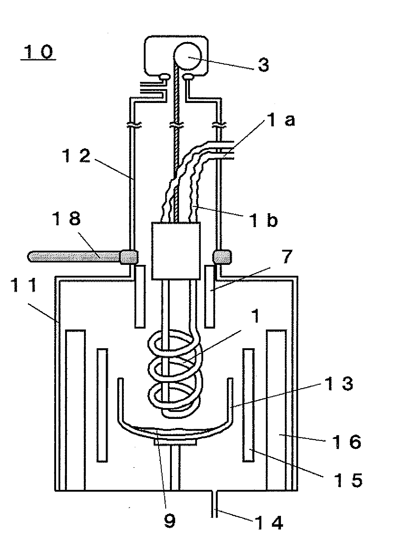
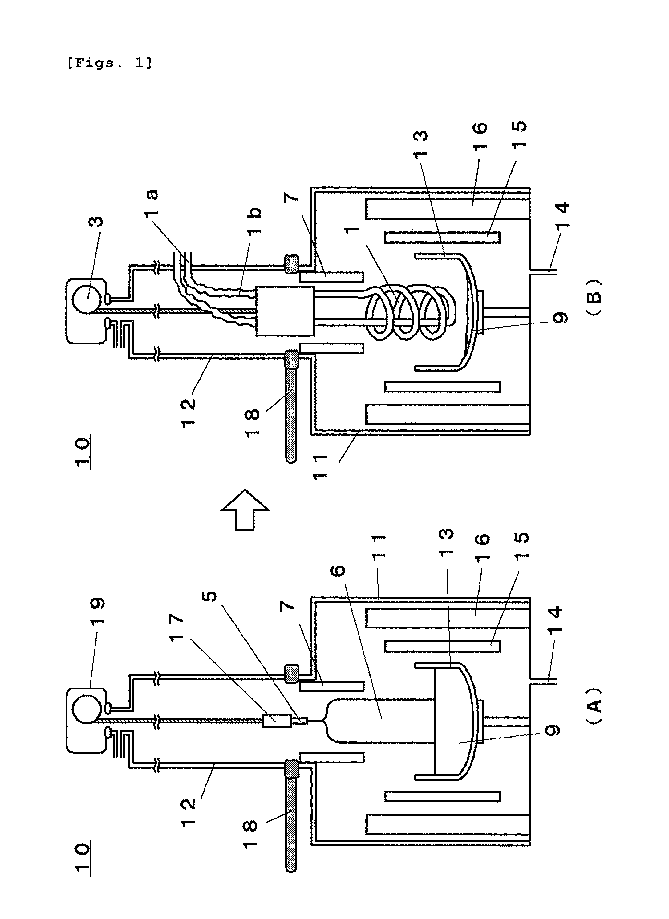
[0090]In the single-crystal manufacturing apparatus 10 shown in FIG. 1 according to the present invention, a cooling time for hot zone components was measured as follows.

[0091]As a crucible in the single-crystal manufacturing apparatus used in this Example 1, a crucible having a diameter of approximately 600 mm for pulling a single crystal having a diameter of 200 mm was utilized. Furthermore, a quartz crucible of this size was utilized to melt a raw material polycrystal for 12 hours, and a single crystal having a diameter of approximately 200 mm and a straight body length of approximately 1 m was grown for 24 hours. After end of growth of the single crystal, a heater was turned off, the crystal was taken out from a pull chamber, then a temperature of a graphite crucible that supports the quartz crucible was measured, and a result was approximately 800° C.

[0092]Then, coolant water having a temperature of approximately 20° C. was circulated in a cooling pipe, and the cooling pipe was...

example 2

[0095]In regard to a melting time and meltage of a raw material, a diameter and a length of a straight body of a grown single crystal, and a growth time, the same conditions as those in Example 1 were used.

[0096]Then, coolant water having a temperature of approximately 20° C. was circulated in a cooling pipe, the cooling pipe was moved down to a position which is immediately above a raw material melt remaining in a crucible and at which the cooling pipe scarcely touches the raw material melt, and an argon gas having an ordinary temperature was circulated from a gas introduction opening. Accordingly, radiation cooling using the cooling pipe was combined with convection cooling using a cooling gas to cool down hot zone components. The same single-crystal manufacturing apparatus as that in Example 1 was used, and cooling using a cooling cylinder for cooling the single crystal was continued.

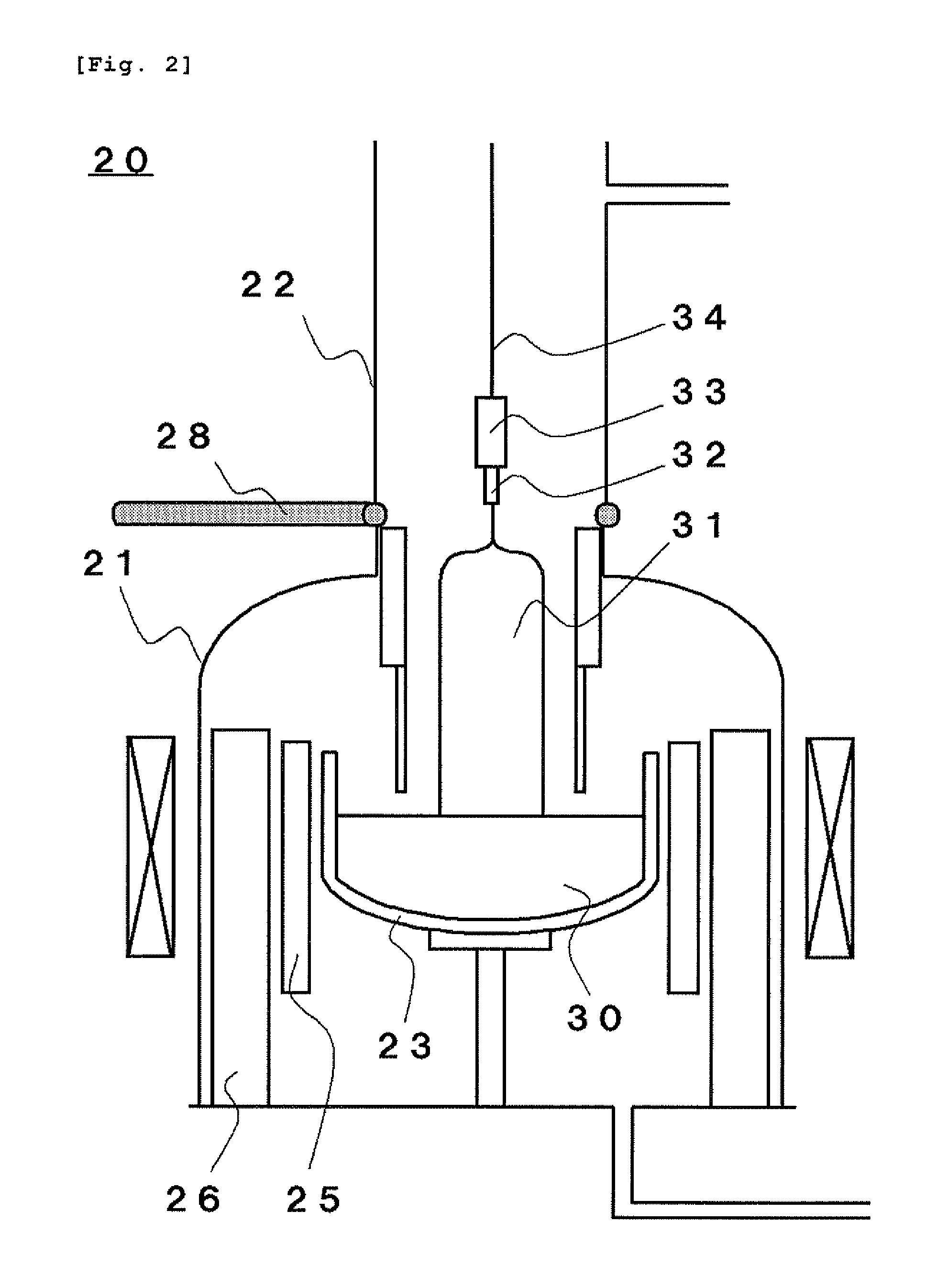
[0097]FIG. 3 shows a result of measuring a temperature of a graphite crucible 13 as a representat...


PUM


Abstract

According to the present invention, there is provided a single-crystal manufacturing apparatus based on Czochralski method, comprising at least: a main chamber configured to accommodate hot zone components including a crucible; and a pull chamber configured to accommodate and take out a single crystal pulled from a raw material melt contained in the crucible, wherein the apparatus further comprises: a cooling pipe which is arranged above the crucible and in which a cooling medium is circulated; and a moving mechanism that moves up and down the cooling pipe, and the hot zone components are cooled down by utilizing the moving mechanism to move down the cooling pipe toward the crucible after growth of the single crystal, and a method for manufacturing a single crystal is also provided. As a result, there can be provided the single crystal manufacturing apparatus and the method for manufacturing a single crystal that enable cooling the hot zone components in the main chamber in a short time after pulling a single crystal having a large diameter, e.g., approximately 200 mm or above.

Description

TECHNICAL FIELD[0001]The present invention relates to a single-crystal manufacturing apparatus and a method for manufacturing a single crystal that can pull up a single crystal having a large diameter, e.g., a diameter of approximately 200 mm (8 inches) or above by Czochralski method (which will be also referred to as CZ method hereinafter) and then cool a hot zone component.BACKGROUND ART[0002]In recent years, to improve performance and reduce a manufacturing cost of a semiconductor device such as a solar cell or an MOS (Metal Oxide Semiconductor) transistor, an increase in diameter of a wafer formed of, e.g., silicon that is used as a substrate has advanced. Therefore, a single-crystal ingot which is grown by, e.g., CZ method and has a diameter of 200 mm (8 inches) or a diameter of 300 mm (12 inches) is manufactured, and an increase in diameter and an increase in weight advance.[0003]Such a single-crystal ingot is manufactured by, e.g., a single-crystal manufacturing apparatus dep...

Claims


Application Information

Patent Timeline
IPC IPC(8): C30B15/00
CPCY10T117/1068C30B15/14
Inventor ABE, TAKAO
Owner SHIN-ETSU HANDOTAI CO LTD
Why Eureka
Try Eureka