Fluid processing apparatus and processing method

a technology of processing apparatus and fluid, which is applied in the direction of machine/engine, grain treatment, pipe heating/cooling, etc., can solve the problems of affecting the flow path of microwaves, the inability of pumps to make it possible to feed fluid, and the number of devices

Active Publication Date: 2010-12-23
M TECH CO LTD
View PDF4 Cites 14 Cited by
  • Summary
  • Abstract
  • Description
  • Claims
  • Application Information

AI Technical Summary

Benefits of technology

[0029]According to each aspect of the invention, even if the process is carried out by a reaction accompanied by separation at high reaction speed, a problem such that substances to be separated would cause clogging in the vicinity of the opening in the processing surfaces can be solved, and further the disturbance of a spiral laminar flow that is a fluid formed between the processing surfaces, due to the flow of a fluid introduced through the opening, can be minimized. Accordingly, intended favorable results such as homogeneous processing and formation of microparticles can be obtained. Here, the micropump effect according to the present invention produces an effect such that a force is generated in the direction of separating the processing surfaces from each other by rotating the processing surfaces provided with a depression, and further a fluid is introduced into the processing surfaces.
[0064]According to the invention of the present application, it is possible to improve speed of temperature homogenization, speed of homogenization of concentration, and to reduce processing time, upon processing in a micro flow path more than ever by giving a temperature gradient to processing surfaces to carry out processing in an apparatus wherein a first fluid containing a material to be processed is introduced between the processing surfaces in processing members capable of approaching to and separating from each other, at least one of which rotates relative to the other, and a second fluid containing a material to be processed is introduced between the processing surfaces from another flow path that is independent of the flow path for introducing the first fluid and is provided with an opening leading to the processing surfaces, whereby the two fluids are processed by mixing and stirring between the processing surfaces. Accordingly, the present invention can provide a fluid processing apparatus and a processing method capable of carrying out more stable and uniform processing compared to the apparatus in Patent Document 1. Further, even when the distance between the processing surfaces is large, the uniformity between the processing surfaces is not deteriorated and thus the throughput can be further increased.

Problems solved by technology

That is, such high feeding pressure is necessary that a pump making possible to feed a fluid cannot be available.
In the case of a reaction accompanied by separation, there is a problem that a microwave flow path is blocked by clogging of a flow path with a product or bubbles the reaction generates.
Further, it is also a problem that since the reaction fundamentally depends on speed of molecular diffusion, a microscopic space is not effective or applicable to every reaction, and actual attempts of the reaction are required by trial and error, then good results are selected.
The increase in the number of devices leads to an increase in the absolute number of failure causes, and when the problem of clogging or the like actually occurs, it can be very difficult to detect a problem site such as a failure site.
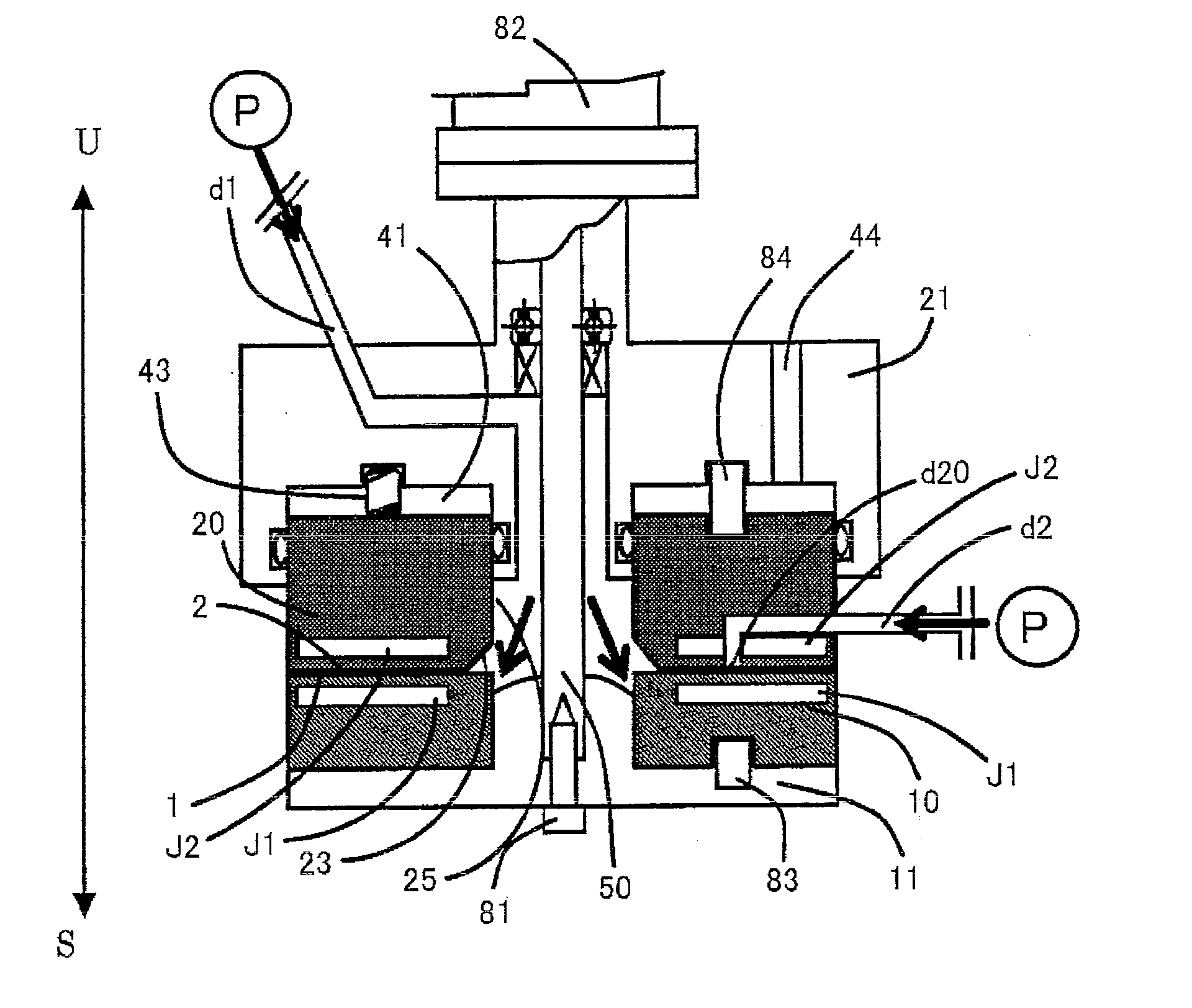
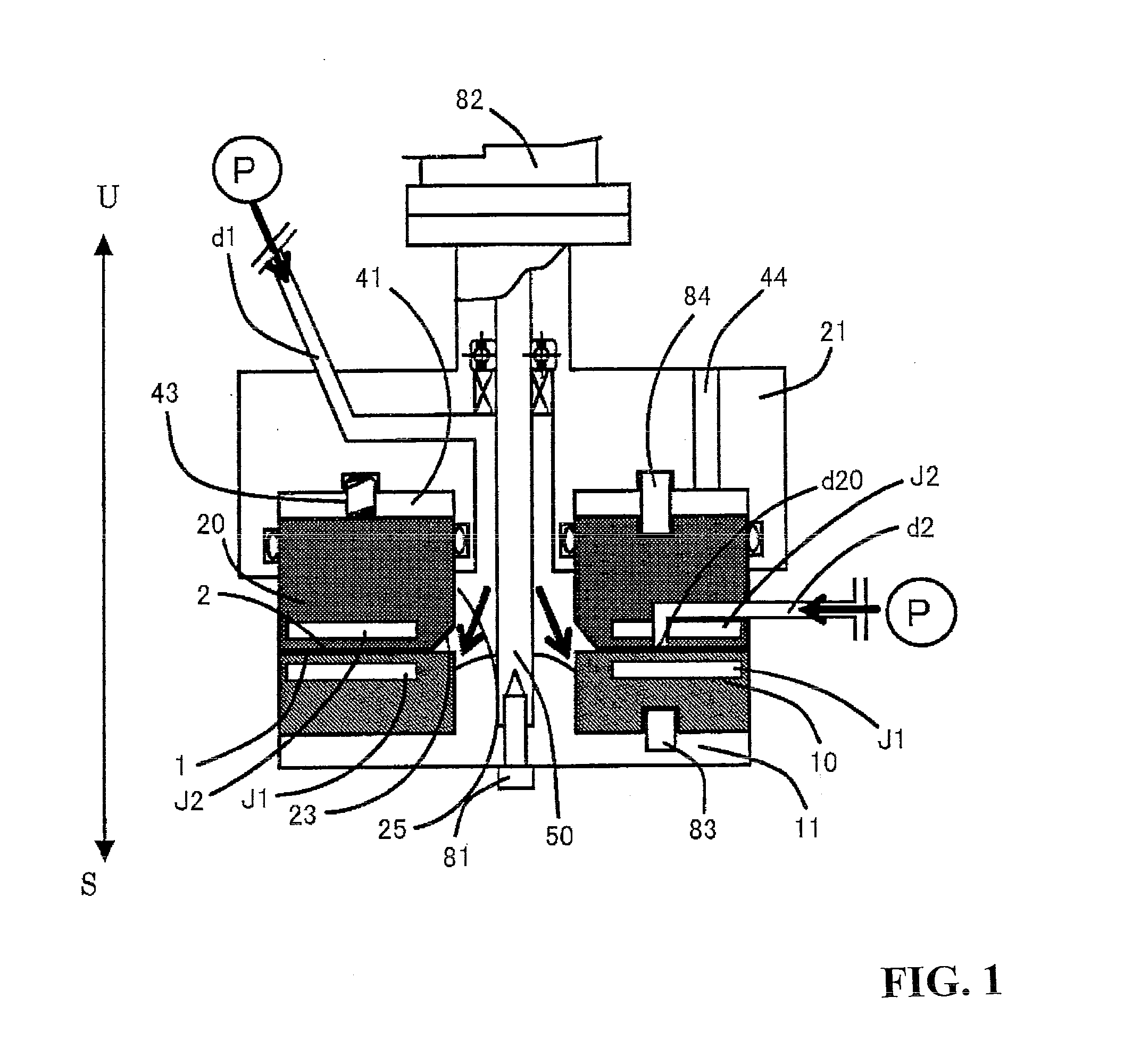
However, even if the apparatus with the mechanism described above is used to process between the processing surfaces, substances to be separated would cause clogging in the vicinity of the opening in the processing surfaces by a reaction accompanied by separation at high reaction speed, and thus the reaction may be interrupted.
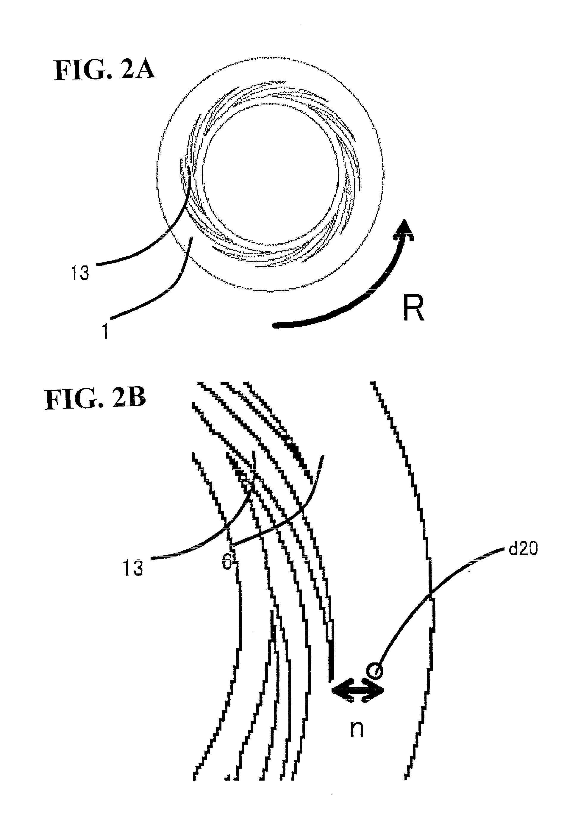
Further, a spiral laminar flow that is a fluid formed between the processing surfaces is disrupted thus often failing to attain intended favorable results such as homogeneous processing and formation of microparticles.
When a total area of the depressions in a horizontal direction is too small against the processing surfaces, effective introduction of the fluid into the processing surfaces from the center of the processing surfaces cannot be achieved.
However, it is not enough to solely consider the volume given by determining the total area and depth of the depressions.
Further, a problem like the above will be caused without providing a specific shape with the depression in order to introduce a fluid evenly.
Favorable results intended in uniform processing and formation of microparticles between the processing surfaces capable of approaching to and separating from each other, at least one of which rotates relative to the other, cannot be obtained without solving these problems.
In a case where various materials to be processed as described above are reacted with one another by simultaneously introducing into the processing surfaces capable of approaching to and separating from each other, at least one of which rotates relative to the other, production of the final processed material E is adversely affected when each of the flow paths independent of the flow for introducing the fluid containing a material A to be processed is arranged in arbitrary places.
That is, there is a problem that in spite of the fact that A, B, C and D are originally reacted in this order to give the product E, this order may not be followed such that the reaction A+B+C→ the product E, the reaction of which is not due to the original reaction process, occurs to produce a different substance.
In contrast, the processed materials may not be efficiently contacted with one another, and thus the reaction may not be carried out, or a substance in poor production such as a processed material B′ may be generated, or the yield of the product E may be decreased, so that there is a problem that the objective particle diameter, crystal form, and molecular structure may not be obtained.
When the processed material after being processed needs to be, for example, temperature-controlled, its mechanism is not concretely established, so there is a problem that the material is subjected once to change in temperature.
On the other hand, when a fluid is processed between processing surfaces in the apparatus with the mechanism shown in Patent Document 4, improvement on speed of temperature homogenization, improvement on speed of homogenization of concentration, and reduction in processing time in support of molecular diffusion, which have been attempted as described above, cannot be completely achieved if the processing with stirring and mixing is carried out only with a spiral laminar flow between the processing surfaces.

Method used


Image

  • Fluid processing apparatus and processing method
  • Fluid processing apparatus and processing method
  • Fluid processing apparatus and processing method

Examples


Embodiment Construction

[0095]Hereinafter, preferable embodiments of the present invention will be described with reference to the drawings. FIG. 1 is a schematic sectional view of a fluid processing apparatus wherein materials to be processed are reacted between processing surfaces, at least one of which rotates relative to the other, and which are capable of approaching to and separating from each other. FIG. 2(A) is a schematic plane view of the first processing surface in the apparatus shown in FIG. 1, and FIG. 2(B) is an enlarged view of an important part of the processing surface in the apparatus shown in FIG. 1. FIG. 3(A) is a sectional view of the second introduction path, and FIG. 3(B) is an enlarged view of an important part for explaining the second introduction path.

[0096]In FIG. 1, arrows U and S show upward and downward directions respectively.

[0097]In FIG. 2(A) and FIG. 3(B), arrow R shows the direction of rotation.

[0098]In FIG. 3(B), arrow C shows the direction of centrifugal force (radial ...


PUM


Abstract

A fluid is processed between processing surfaces capable of approaching to and separating from each other, at least one of which rotates relative to the other. A first fluid containing a material to be processed is introduced between processing surfaces 1 and 2, by using a micropump effect acting with a depression 13 arranged on the processing surfaces from the center of the rotating processing surfaces. A second fluid containing a material to be processed, independent of this introduced fluid, is introduced from another fluid path d2 that is provided with an opening d20 leading to the processing surfaces, whereby the processing is done by mixing and stirring between the processing members 1 and 2. In a plane along the processing surfaces, directionality accompanies the introducing direction from the opening of the second fluid into the processing surfaces. Regarding the introducing direction of the second fluid, it is an outward direction away from the center for the fluid in the radial direction on the processing surface, and it is a forward direction for the fluid in the rotation direction of the fluid between the rotating processing surfaces.

Description

TECHNICAL FIELD[0001]The present invention relates to a fluid processing apparatus wherein a material to be processed is processed between processing surfaces in processing members capable of approaching to and separating from each other, at least one of which rotates relative to the other.BACKGROUND ART[0002]Patent Document 1: JP-A 2006-104448[0003]Patent Document 2: JP-A 2003-159696[0004]Patent Document 3: JP-A 2003-210957[0005]Patent Document 4: JP-A 2004-49957[0006]Non-Patent Document 1: “Microreactor: Synthesis Technology in New Age”, supervised by Junichi Yoshida, CMC Publishing Co., Ltd.[0007]Non-Patent Document 2: X. F. Zhang, M. Enomura, M. Tsutahara, K. Takebatashi, M. Abe “Surface Coatings International Prat B: Coatings Transactions,” Vol. 89, B4, 269-274, December 2006[0008]A microreactor or a micromixer has been provided as a fluid processing apparatus using a fine flow path or a fine reaction container. There is possibility that the microscopic reaction field given by ...

Claims


Application Information

Patent Timeline
Patent Type & Authority Applications(United States)
IPC IPC(8): F15D1/00B01F25/60B01F27/93B01J19/00B02C7/08B02C7/11B02C7/12
CPCB01F7/00758B01F7/00791B01J19/10B01J19/123B01J19/0093B01J2219/00094B01J2219/00137C09B67/0022C09B67/0091B01J19/1887Y10T137/85978Y10T137/8593Y10T137/0396Y10T137/6416B01F27/271B01F27/2714B01J19/00C09B67/0014B01F27/93
Inventor ENDMURA, MASAKAZU
Owner M TECH CO LTD
Why Eureka
Try Eureka