

Electromagnetic Interference Suppression Flat Yarn, Electromagnetic Interference Suppression Article Using the Flat Yarn, and Method for Manufacturing the Flat Yarn and Article Using the Same
- Summary
- Abstract
- Description
- Claims
- Application Information
AI Technical Summary
Benefits of technology
Problems solved by technology
Method used
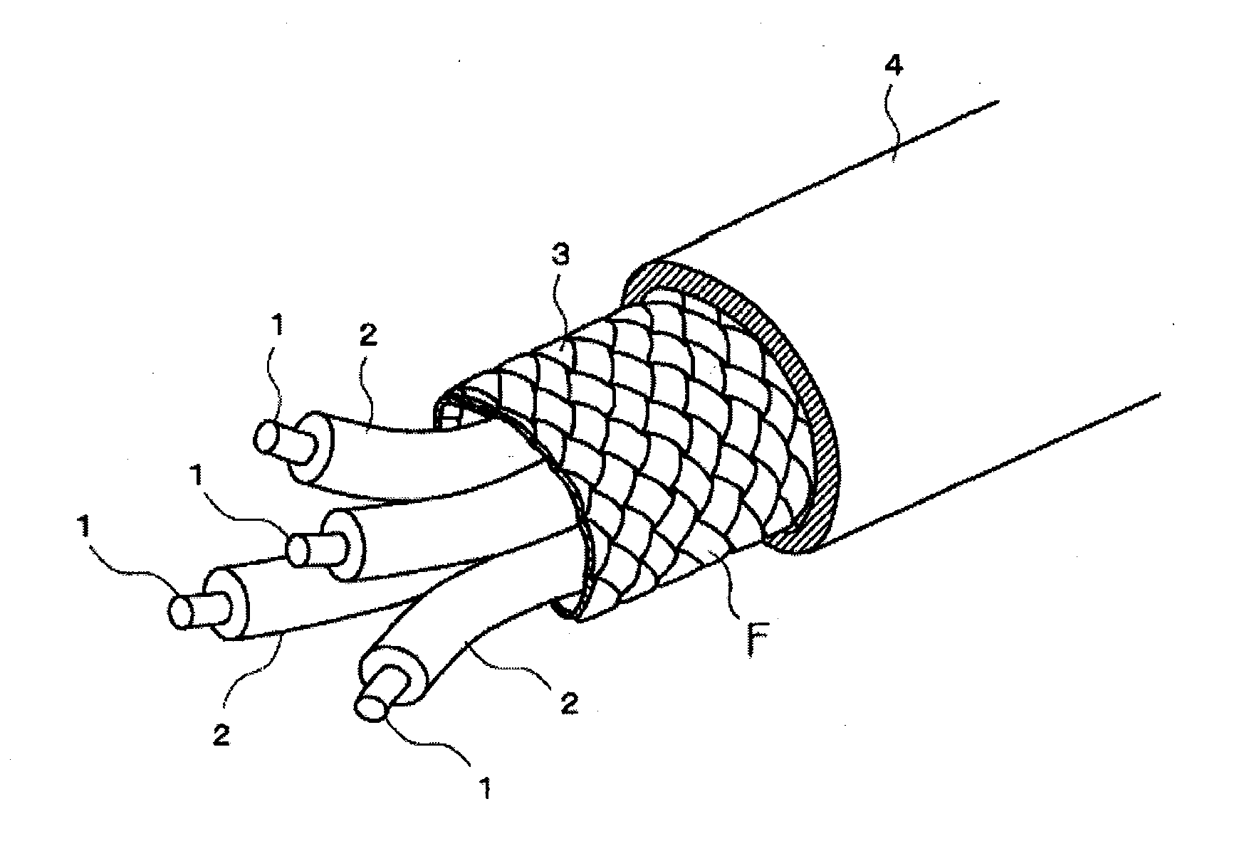
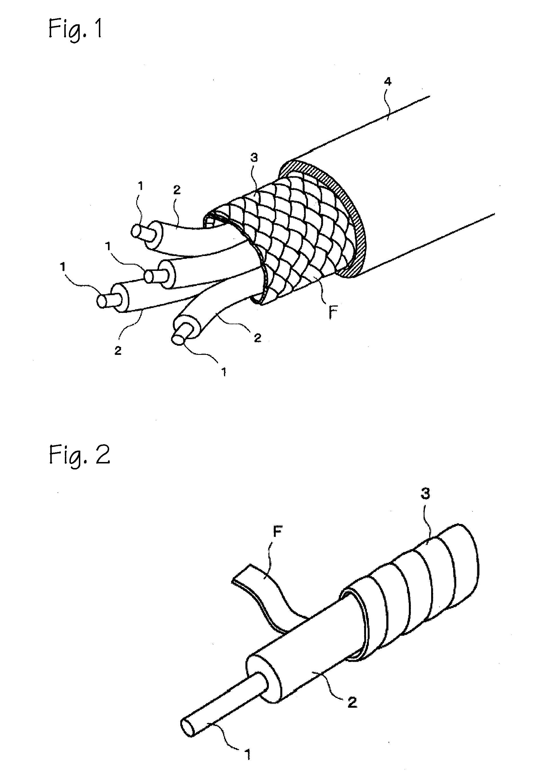
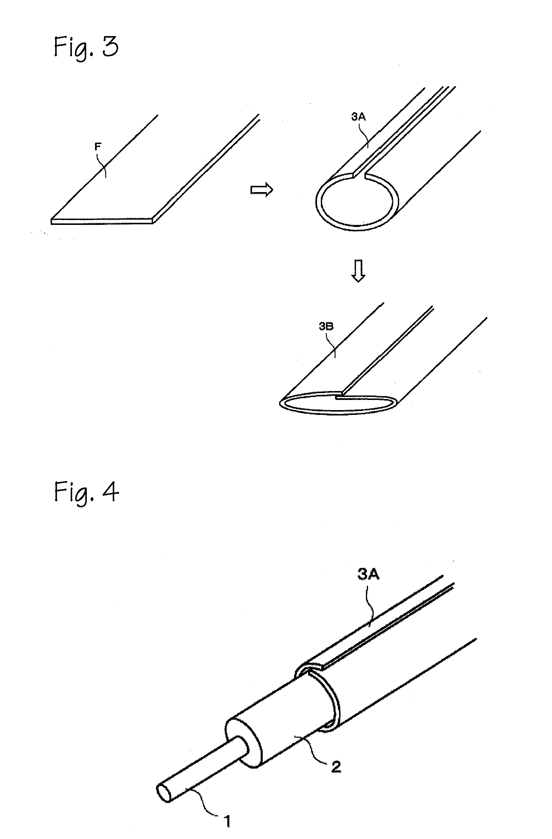
Image

Examples
example 1
[0091]Fe3O4 powder (magnetite powder) was used as a metal powder and ground with a grinder, after which the ground powder was classified to remove large coarse particle. The resulting powder had an average particle size of 5 μm.
[0092]300 Parts by weight of the magnetite powder after classification, 100 parts by weight of a carbon black powder as a conductive material, and 100 parts by weight of a polyurethane dissolved in 300 parts by weight of N,N-dimethylformamide (DMF), 30 parts by weight of toluene, and 170 parts by weight of methyl ethyl ketone (MEK) were mixed with stirring, thus giving a solution of an EMI absorbing polymer resin composition.
[0093]The resulting solution of the EMI absorbing polymer resin composition was applied to a release paper using a doctor blade, and dried at 140° C. for 3 minutes, thus giving an EMI absorbing polymer resin layer (I) with a thickness of 60 μm.
[0094]Further, 100 parts by weight of a polyurethane resin dissolved in 150 parts by weight of D...
example 2
[0100]100 Parts by weight of a carbon black powder as a conductive material, and 100 parts by weight of a polyurethane resin dissolved in 300 parts by weight of DMF, 30 parts by weight of toluene, and 170 parts by weight of MEK, were mixed with stirring, thus giving a solution of an EMI absorbing polymer resin composition.
[0101]The resulting solution of the EMI absorbing polymer resin composition was applied to a 25 μm thick polyester (PET) film (Unitika; “S-25”), i.e., a polymer resin layer (II), using a doctor blade, and dried at 140° C. for 3 minutes, thus giving an EMI absorbing polymer resin layer (I) with a thickness of 50 μm.
[0102]Further, 100 parts by weight of a polyurethane resin dissolved in 150 parts by weight of DMF and 100 parts by weight of toluene, 130 parts by weight of melamine cladding ammonium polyphosphate as a flame retardant, and 170 parts by weight of MEK as a solvent were mixed with stirring to give a polyurethane solution, and the polyurethane solution was ...
example 3
[0107]A Fe—Si—Al alloy material as a metal powder was ground to a flat shape in a medium agitation mill using toluene as a solvent, and subsequently classified to remove large coarse particles to give a particle size (D50) of 35 μm. 150 Parts by weight of the thus-obtained flat Fe—Si—Al powder, 100 parts by weight of a carbon black powder as a conductive material, and 100 parts by weight of a polyurethane dissolved in 300 parts by weight of DMF, 30 parts by weight of toluene, and 170 parts by weight of MEK were mixed with stirring to give a solution of an EMI absorbing polymer resin composition.
[0108]The resulting solution of the EMI absorbing polymer resin composition was applied to a 12.5 μm thick polyimide (PI) film (Du Pont-Toray; “Kapton 50H”), i.e., a polymer resin layer (II), using a doctor blade, and dried at 140° C. for 3 minutes to give an EMI absorbing polymer resin layer (I) with a thickness of 50 μm, thereby yielding a two-layered EMI suppression film with a thickness o...
PUM
| Property | Measurement | Unit |
|---|---|---|
| Frequency | aaaaa | aaaaa |
| Frequency | aaaaa | aaaaa |
| Mass | aaaaa | aaaaa |
Abstract
Description
Claims
Application Information