Control apparatus for fuel reformer

a technology of control apparatus and fuel reformer, which is applied in the direction of electrical control, exhaust treatment electric control, instruments, etc., can solve the problems of increasing the cost of fuel reformer, so as to suppress the excessive consumption of fuel

Inactive Publication Date: 2010-12-23
HONDA MOTOR CO LTD
View PDF5 Cites 14 Cited by
  • Summary
  • Abstract
  • Description
  • Claims
  • Application Information

AI Technical Summary

Benefits of technology

[0053]According to this configuration, in a case of the operating state of the fuel reformer being a steady state, the conversion function setting parameter is set within the range of −1 to 0 to a value closer to −1 than 0. In particular, this enables excessive consumption of fuel to be suppressed when temperatures rise, and enables overshoot of the temperature of the reforming catalyst to be suppressed.

Problems solved by technology

Compared to gasoline, diesel in particular contains hydrocarbons having high carbon numbers and is difficult to break down, and it is difficult to cause to react equally over the wide range of the constituent ratios of hydrocarbon molecules; therefore, it is easy for carbon to deposit on the catalyst.
However, if steam is supplied in excess, a large amount of external energy is necessary in order to produce hydrogen due to the thermal efficiency declining.
In addition, if oxygen is supplied in excess, the yield of hydrogen will decline due to excessive combustion, and the activity of the catalyst will decline due to excessive temperature rise and may deactivate depending on the situation.
As a result, the time required in activation of the reforming catalyst may increase, and the emission amount of unreacted hydrocarbons may increase.
In addition, since the detection section of the temperature sensor is exposed to steam and reducing gas of high temperature, it is necessary to improve the durability in order to prevent corrosion and degradation; however, in this case, the responsiveness will decline.
As a result, in a case of using a temperature sensor in the fuel reformer, the aforementioned detection delay becomes obvious.
As a result, the time required in activation of the reforming catalyst may increase, and the emitted amount of unreacted hydrocarbons may increase.
As described above, temperature control that matches degradation of the reforming catalyst is difficult with the first and second techniques.

Method used


Image

  • Control apparatus for fuel reformer
  • Control apparatus for fuel reformer
  • Control apparatus for fuel reformer

Examples


Embodiment Construction

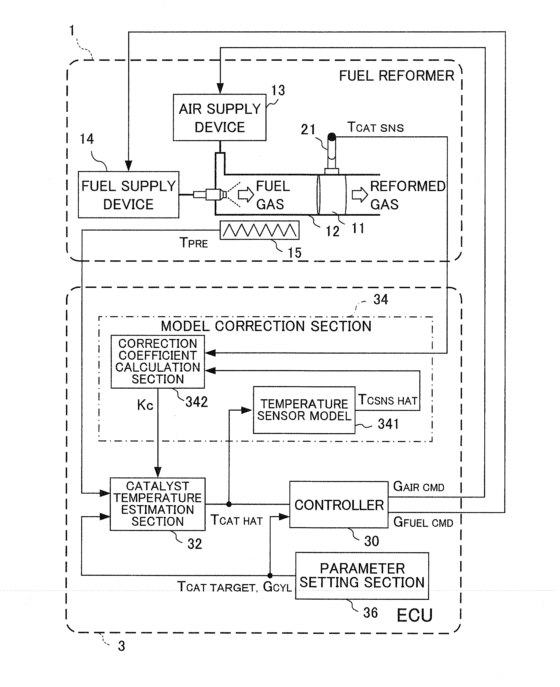
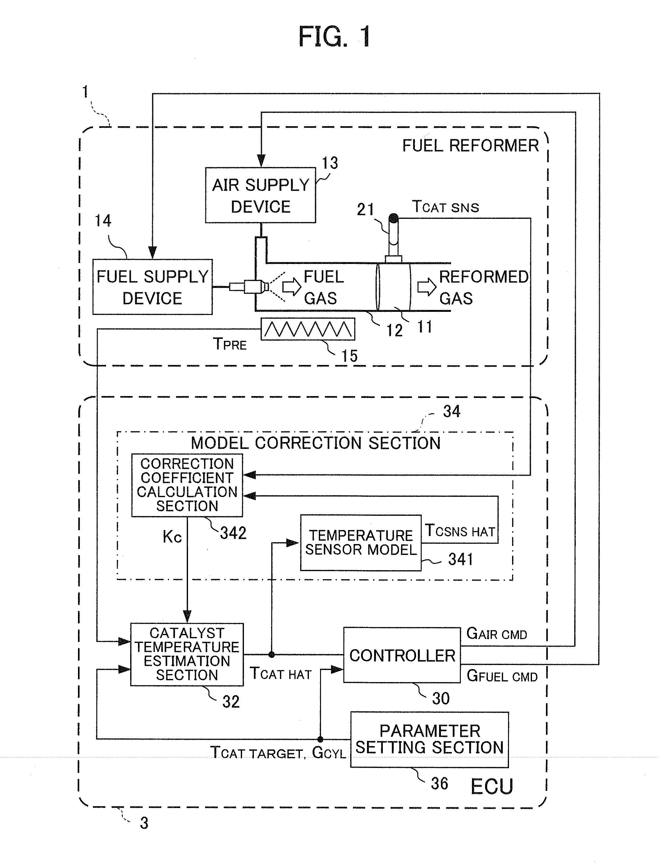
[0083]FIG. 1 is a schematic diagram showing a configuration of a fuel reformer 1 and an electronic control unit (hereinafter referred to as “ECU”) 3 as a control apparatus thereof relating to an embodiment of the present invention.

[0084]The fuel reformer 1 is configured to include a gas channel 12 of a cylindrical shape in which a reforming catalyst 11 is provided inside thereof, and an air supply device 13 and fuel supply device 14 that supply air and fuel from an end side of this gas channel 12. Specifically, this fuel reformer 1 is of straight-flow type in which the flow of gas on an inlet side of the reforming catalyst 11 and a flow of gas on an outlet side of the reforming catalyst 11 are the same direction.

[0085]The air supply device 13 is configured by a compressor, valve, and the like, which are not illustrated, and supplies air into the gas channel 12 in accordance with a control signal (GAIR CMD) output from the ECU 3.

[0086]The fuel supply device 14 is configured by a fuel...


PUM


Abstract

Disclosed is a control apparatus for a fuel reformer, which enables control with consideration of the nonlinearity of the thermal model of a reforming catalyst. An ECU (3) comprises a catalyst temperature sensor (21) for detecting the temperature of a reforming catalyst (11), a catalyst temperature estimation section (32) for estimating the catalyst temperature on the basis of a correlation model relating the catalyst temperature to the catalyst reaction thermal coefficient out of plural parameters by which the reforming reaction of the reforming catalyst (11) is characterized, a controller (30) for controlling the temperature of the reforming catalyst (11) according to the estimated temperature TCAT HAT of the catalyst temperature estimation section (32), and a model correction section (34) for defining plural correction weighting functions W0 to W4 with the catalyst temperature as the domain of definition, calculating plural local correction coefficients KCL0 to KCL4 by which the plural correction weighting functions are to be multiplied, respectively, from the detected temperature TCAT SNS of the catalyst temperature sensor (21) and the estimated temperature TCAT HAT of the catalyst temperature estimation section (32), and correcting the correlation model according to the plural correction weighting functions and local correction coefficients.

Description

TECHNICAL FIELD[0001]The present invention relates to a control apparatus for a fuel reformer and, in particular, relates to a control apparatus for a fuel reformer capable of control in which degradation of the reforming catalyst is taken into account.BACKGROUND ART[0002]Hydrogen energy is green energy that has gained attention as a petroleum alternative energy of the future, and in recent years, has been applied as an energy source of fuel cells and internal combustion engines. In the research into internal combustion engines utilizing hydrogen, for example, there is hydrogen engines, hydrogen-boosted engines, reducing agent in NOx purification apparatuses, auxiliary power supplies using fuel cells, and the like. Under these circumstances, a great deal of research is also related to the production of hydrogen.[0003]Methods of producing hydrogen by separating raw materials containing hydrogen atoms such as hydrocarbon fuel, water, and alcohol by way of catalytic reforming, thermal ...

Claims


Application Information

Patent Timeline
Patent Type & Authority Applications(United States)
IPC IPC(8): G05D23/00
CPCC01B3/386Y02T10/36C01B2203/1041C01B2203/1047C01B2203/1082C01B2203/1604C01B2203/1614C01B2203/1619C01B2203/1623F01N3/035F01N9/00F01N9/005F01N2240/30F01N2610/04F01N2900/1602F01N2900/1631F02D41/0027F02D2041/1433F02D2200/0802F02D2200/0804H01M8/0618Y02T10/47F02D19/0628F02D19/0671C01B2203/0261Y02T10/30Y02T10/40Y02E60/50
Inventor IWAMOTO, JUNMIKAMI, HITOSHIMOTOHASHI, GOYASUI, YUJI
Owner HONDA MOTOR CO LTD
Why Eureka
Try Eureka