
Convection enhanced closed loop geothermal heat pump well

Active Publication Date: 2010-12-30
AZTECH ENGINEERS
View PDF21 Cites 12 Cited by
  • Summary
  • Abstract
  • Description
  • Claims
  • Application Information

AI Technical Summary

Benefits of technology

[0012]It is an object of the present invention to provide a new well configuration that will improve the performance of a geothermal, or ground source, heat pump.
[0013]It is an additional object of the present invention to provide a geothermal heat pump that combines the efficiency benefits of open loop systems with the ease, stability and predictability of closed loop systems.
[0014]It is yet another object of the present invention to provide a geothermal heat pump that combines the efficiency benefits of the open loop systems with the ease, stability and predictability of the closed loop systems by adding convection, as well as conduction, to the heat exchange process.

Problems solved by technology

There are problems, however, associated with these known systems.
In particular, although the open loop can be very effective and efficient, an adequate ground water yield (the amount of water that can be taken out of the ground on a sustained basis) is required, re-injection of the water into the earth is very difficult, stringent environmental permitting is often required, adding years and thousands of dollars to a project, and the effect on the local ground water is a concern.
While closed loop systems do not rely on ground water, do not have the same environmental concerns as open loops systems, do not require re-injection, and are more widely used with more reliable and expectable performance, they are also notably less efficient.
Indeed, closed loop heat exchange with the earth is not efficient because it relies only on conduction with a limited radius in which to transfer heat into or from the ground.
As a hybrid of open and closed loop systems, known standing column wells have not achieved their goal of providing the benefits of both open and closed loop systems without the associated drawbacks.
In particular, these wells are generally very deep and, as such, can be difficult to drill.
Although substantial yield is not supposed to be required, some yield for water bleed-off will be necessary if the system cannot keep up.
As such, this type of standing column well may not be code compliant in some jurisdictions.
Moreover, if adequate yield cannot be obtained because of water flow restrictions in the well, the water temperature may fall below freezing, potentially resulting in disastrous freeze-ups.

Method used


Image

  • Convection enhanced closed loop geothermal heat pump well
  • Convection enhanced closed loop geothermal heat pump well
  • Convection enhanced closed loop geothermal heat pump well

Examples


Embodiment Construction

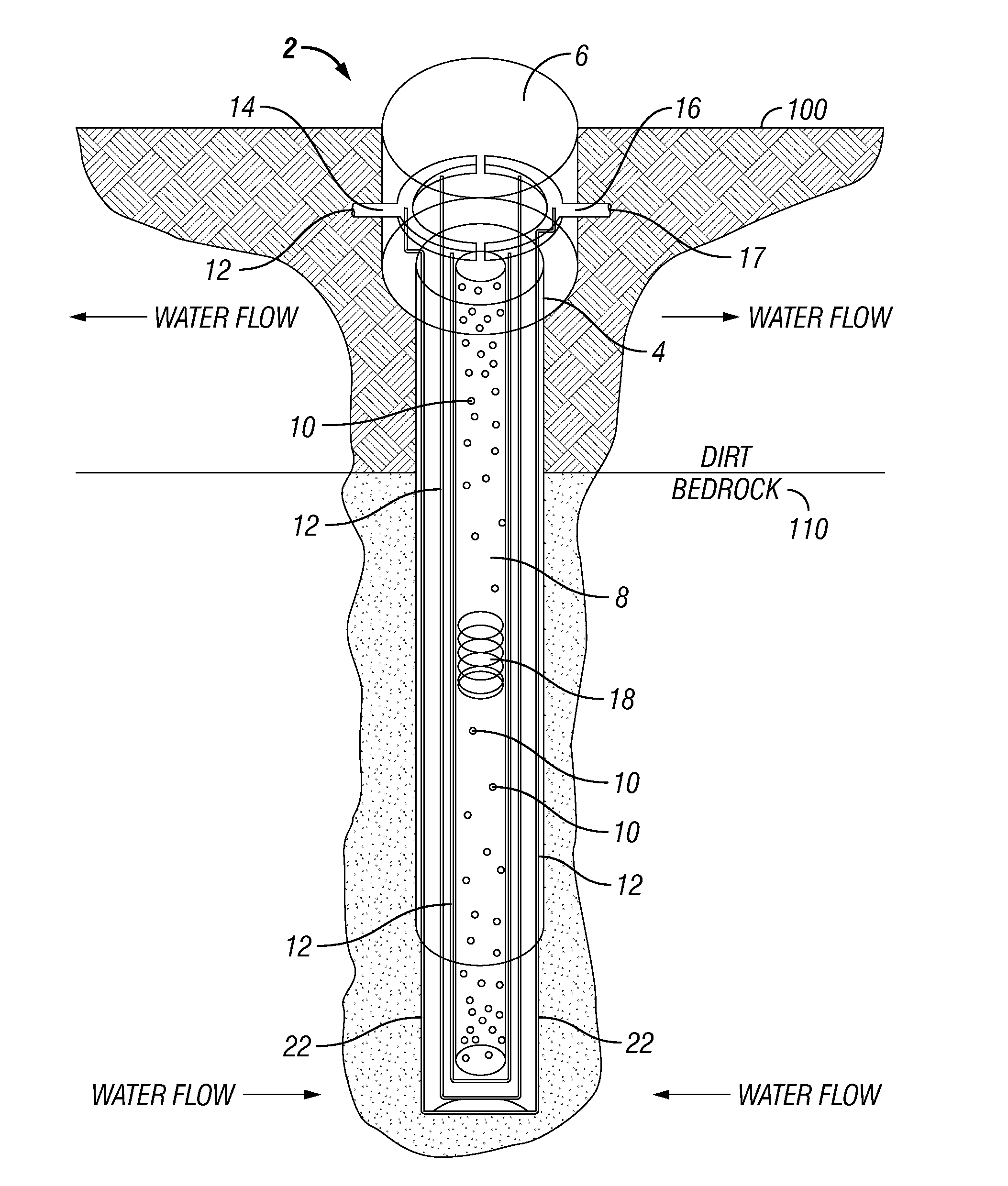
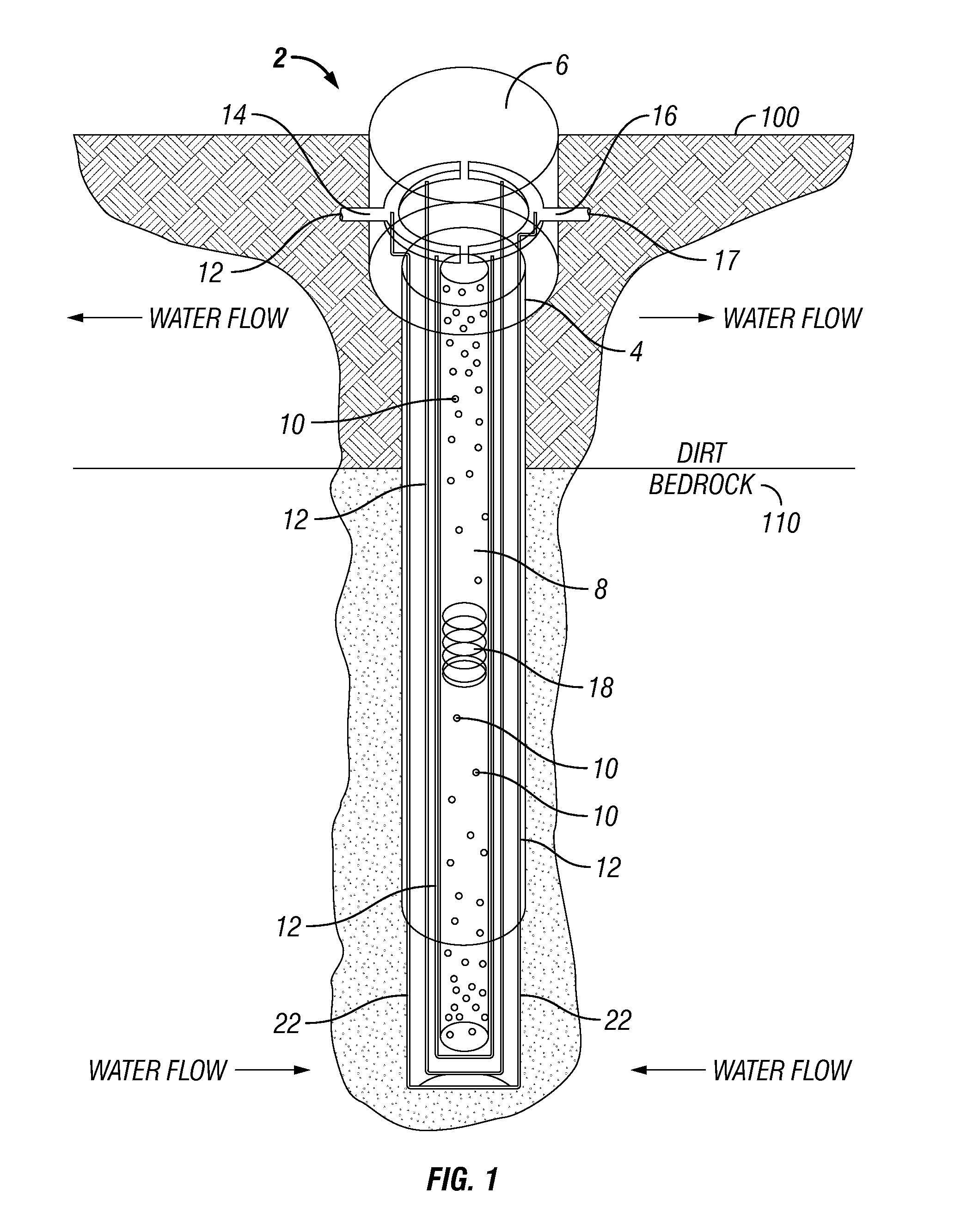
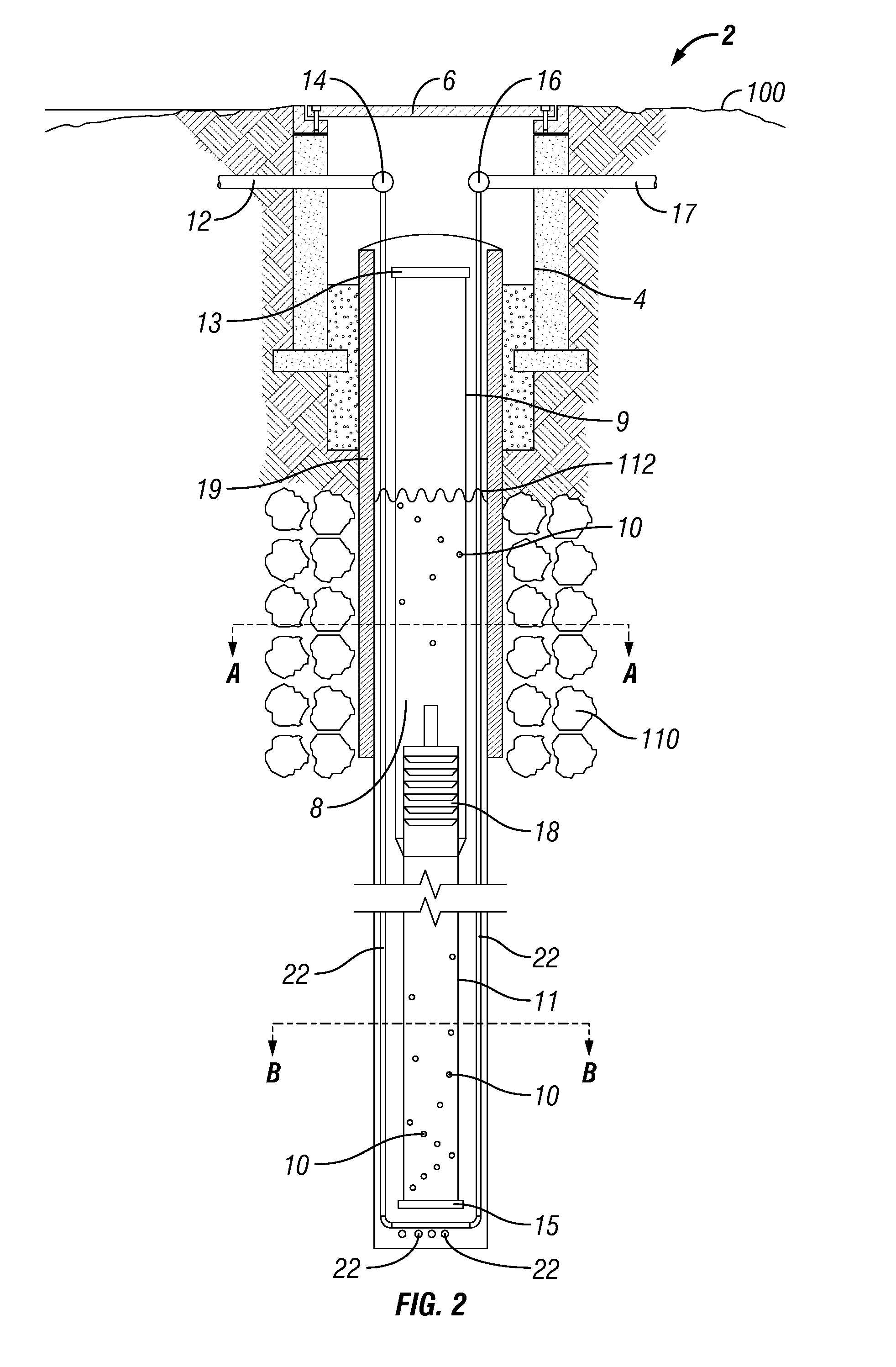
[0022]Referring to FIGS. 1 and 2, a well 2 for serving a geothermal, or ground source, heat pump system according to the present invention, is shown. As shown therein, the well 2 extends substantially vertically down from the surface of the earth into bedrock 110. A manhole 4 with a cover 6 sits on top of the well at grade level 100. As also indicated in FIG. 2, a standard concrete manhole and cast iron cover can also be used to top the well. In the northeastern part of the United States, bedrock is typically expected to start at a depth of 20-50 feet below the earth's surface, with dirt comprising the upper-most layer. Accordingly, to accommodate the well 2 of the present invention, a well hole is bored approximately 450 ft. into the earth, however, other optimum depths are also possible and are dependent on bedrock depth, water level, etc. For the well construction itself, a steel casing 19 is used only where the well extends through the uppermost layer of dirt. The steel casing 1...


PUM


Abstract

An energy transfer system for transferring energy between the earth and a facility comprising a well bore at least partially filled with groundwater, a center pipe having a top end and a bottom end disposed in the well bore and having a plurality of apertures for allowing the ingress and egress of groundwater, a pump disposed within the center pipe for facilitating a flow of groundwater through the apertures, and a closed source loop disposed in the well bore, the source loop including at least one source loop pipe extending adjacent the center pipe in said well bore and containing a working fluid for absorbing or transmitting thermal energy.

Description

CROSS-REFERENCE TO RELATED APPLICATIONS[0001]This application claims the benefit of U.S. Provisional Application Ser. No. 61 / 220,640, filed on Jun. 26, 2009, which is herein incorporated by reference in its entirety.FIELD OF THE INVENTION[0002]The present invention relates generally to a geothermal heat pump and well and more specifically to a geothermal heat pump well that combines the efficiency benefits of an open loop heat pump with the ease, stability and predictability of a closed loop heat pump.BACKGROUND OF THE INVENTION[0003]Heat pumps and / or air conditioners essentially move thermal energy from one location to another, i.e., from a heat source to a heat sink. A heat pump varies from an air conditioner in that it can reverse the direction of thermal transfer, changing the source to the sink, and the sink to the source, thus being able to provide cooling in the summer and heating in the winter. The vapor compression refrigeration cycle, which is currently used for most cooli...

Claims


Application Information

Patent Timeline
IPC IPC(8): F24J3/08
CPCF24J3/08Y02E10/16F24T10/10F24T10/15F24T10/30Y02E10/10
Inventor AZZAM, DEAN H.
Owner AZTECH ENGINEERS
Learn More