
Ion Source Cleaning End Point Detection

a technology of end point detection and ion source cleaning, which is applied in the direction of particle separator tube details, separation process, therapy, etc., can solve the problems of unstable source operation, low vapor pressure of species, and condense and adhere to the surface of the ion source,

Active Publication Date: 2010-12-30
VARIAN SEMICON EQUIP ASSOC INC
View PDF5 Cites 13 Cited by
  • Summary
  • Abstract
  • Description
  • Claims
  • Application Information

AI Technical Summary

Problems solved by technology

These unwanted species typically have low vapor pressure and may condense and adhere to the interior surfaces of the source chamber.
These solid deposits may change the electrical characteristics (voltage instability) of the chamber walls and possibly interfere with the ion source aperture from which the ions are extracted, thereby causing unstable source operation and non-uniform beam extraction.
However, using RGAs for endpoint detection requires an additional piece of equipment other than the implanter itself.
In addition, RGAs do not detect the ions created in and extracted from the ion source, but detect neutral gas atoms and molecules originating from all regions in the vacuum system.

Method used


Image

  • Ion Source Cleaning End Point Detection
  • Ion Source Cleaning End Point Detection
  • Ion Source Cleaning End Point Detection

Examples


Embodiment Construction

[0015]The present invention will now be described more fully hereinafter with reference to the accompanying drawings, in which preferred embodiments of the invention are shown. This invention, however, may be embodied in many different forms and should not be construed as limited to the embodiments set forth herein. Rather, these embodiments are provided so that this disclosure will be thorough and complete, and will fully convey the scope of the invention to those skilled in the art. In the drawings, like numbers refer to like elements throughout.

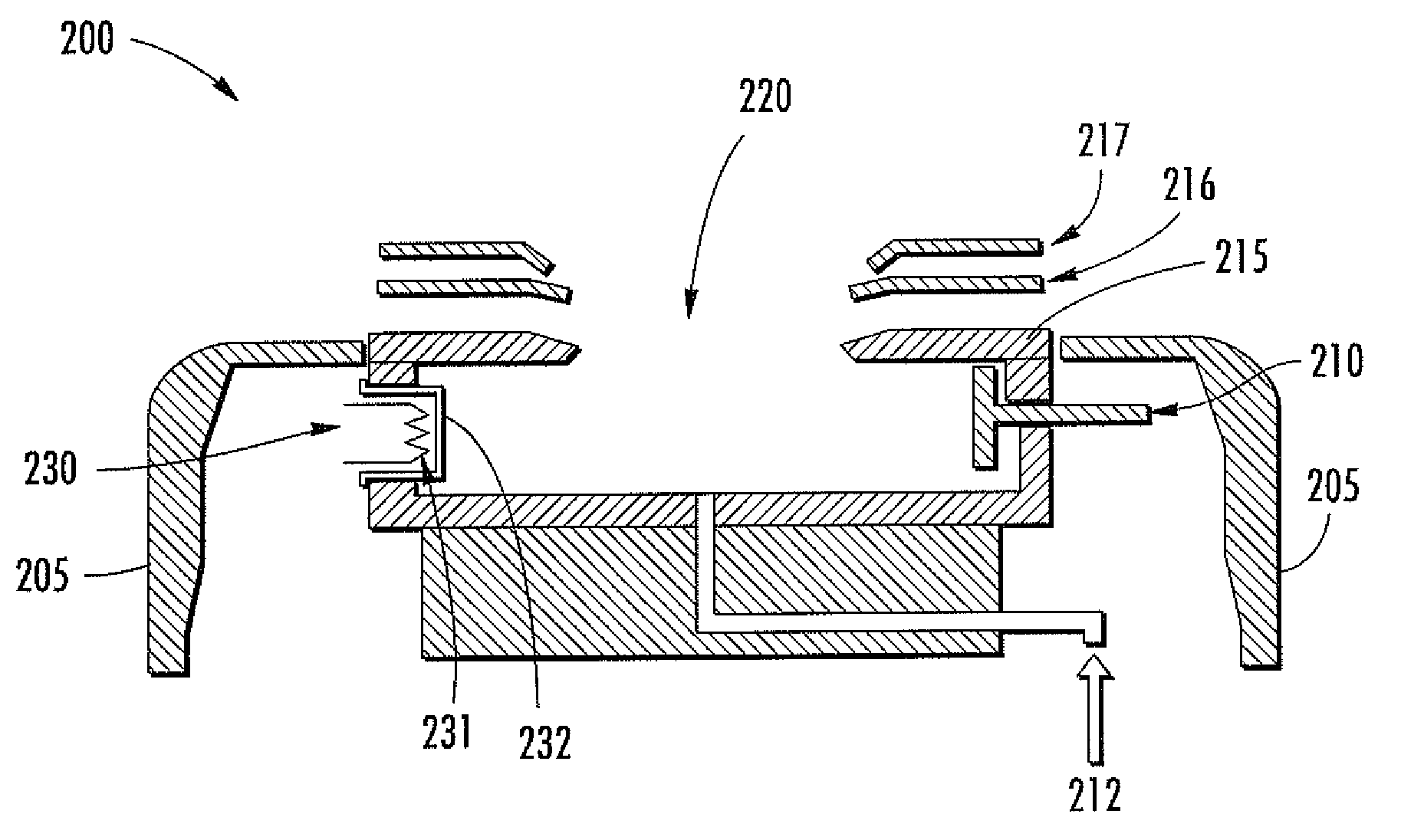
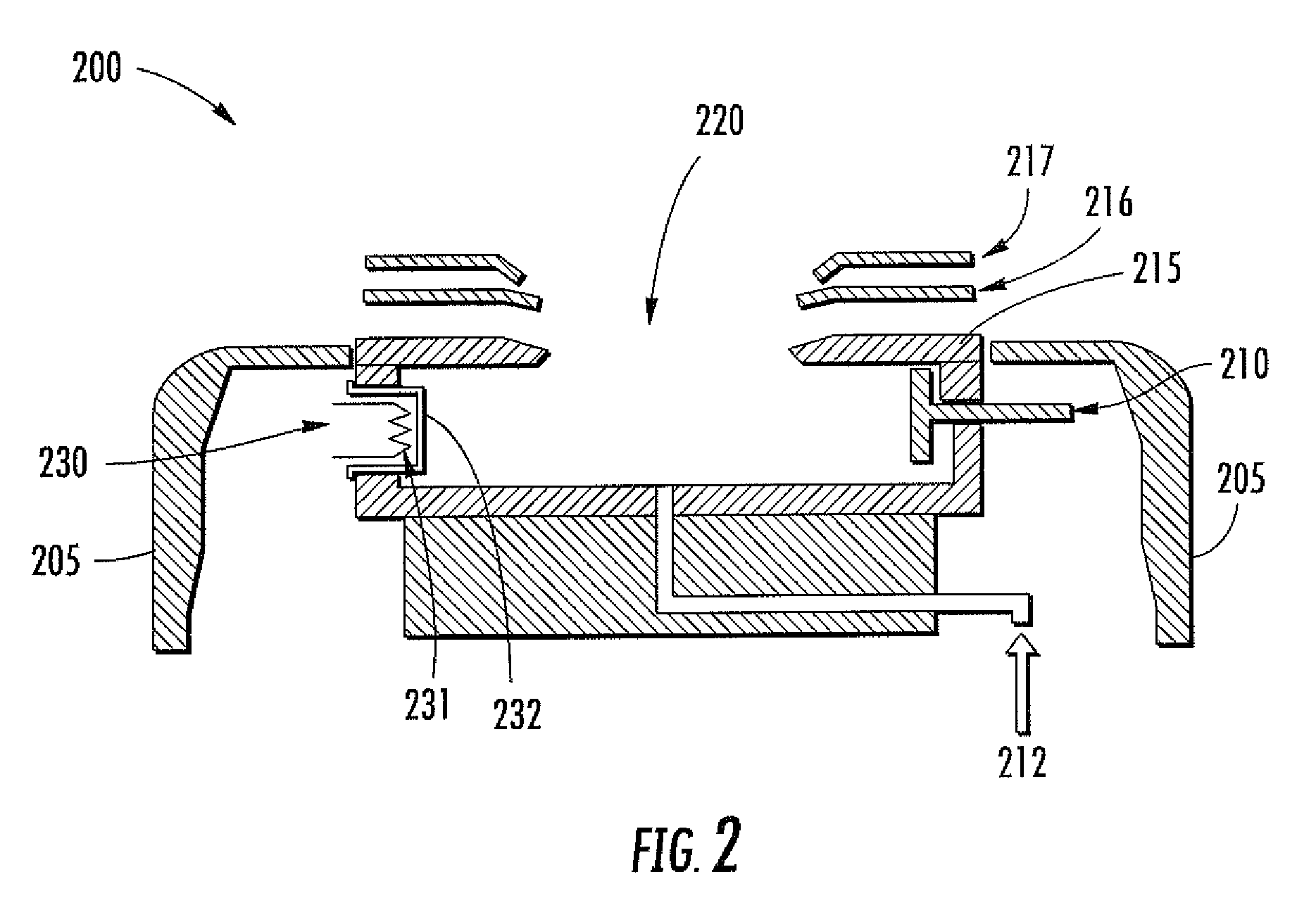
[0016]FIG. 2 is a cross sectional block diagram generally illustrating an ion source chamber 200 used to generate ions for implantation into a substrate. Chamber 200 includes aperture 220 through which ions are extracted. The interior walls of chamber 200 are electrically conductive (e.g. tungsten) and define an ionization zone within which energy is imparted to a dopant gas having source elements such as, for example, phosphorous (P) and ...


PUM

PropertyMeasurementUnit
Electrical conductivityaaaaaaaaaa
Ratioaaaaaaaaaa
Mass spectrumaaaaaaaaaa

Abstract

In an ion implanter, a Faraday cup is utilized to receive an ion beam generated during ion source cleaning. The detected beam has an associated mass spectrum which indicates when the ion source cleaning process is complete. The mass spectrum results in a signal composed of a cleaning agent and the material comprising the ion source. This signal will rise over time as the ion source chamber is being cleaned and will level-off and remain constant once the deposits are etched away from the source chamber, thereby utilizing existing implant tools to determine endpoint detection during ion source cleaning.

Description

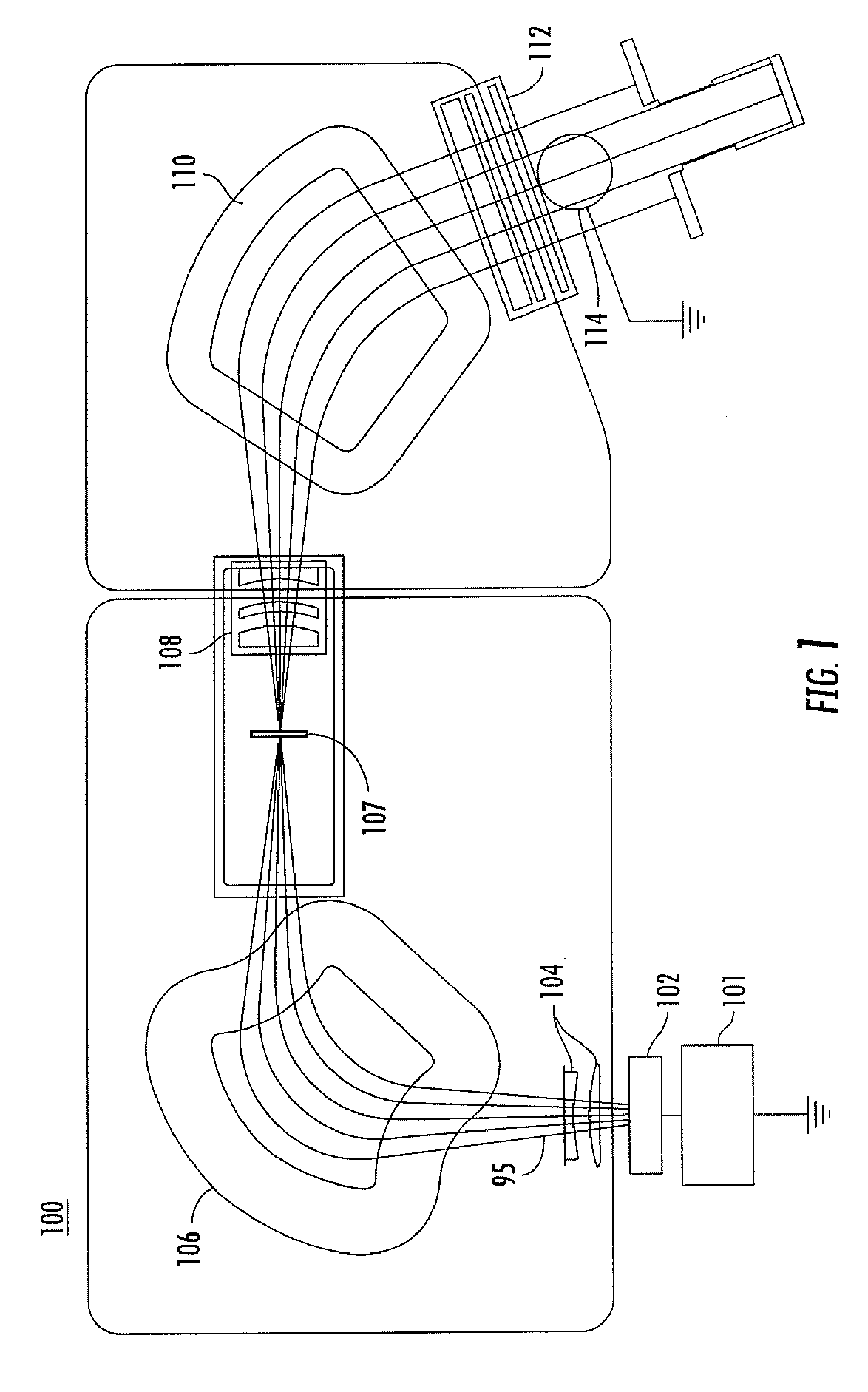
BACKGROUND OF THE INVENTION[0001]1. Field of the Invention[0002]Embodiments of the invention relate to the field of semiconductor device fabrication. More particularly, the present invention relates to an apparatus and method for cleaning an ion source chamber used in ion implantation equipment.[0003]2. Discussion of Related Art[0004]Ion implantation is a process used to dope impurity ions into a semiconductor substrate to obtain desired device characteristics. An ion beam is directed from an ion source chamber toward a substrate. The depth of implantation into the substrate is based on the ion implant energy and the mass of the ions generated in the source chamber. FIG. 1 is a block diagram of an ion implanter 100 including an ion source chamber 102. A power supply 101 supplies the required energy to source 102 which is configured to generate ions of a particular species. The generated ions are extracted from the source through a series of electrodes 104 and formed into a beam 95 w...

Claims


Application Information

Patent Timeline
IPC IPC(8): H01J37/317H01J37/05H01J49/26
CPCH01J27/02H01J37/08H01J37/3171H01J2237/30466H01J2209/017H01J2237/022H01J2237/05H01J49/10H01J2237/3175
Inventor PLATOW, WILHELM P.BASSOM, NEIL J.KURUNCZI, PETER F.PEREL, ALEXANDER S.CHANEY, CRAIG R.
Owner VARIAN SEMICON EQUIP ASSOC INC
Learn More