
Image processor, image processing method, digital camera, and imaging apparatus

a technology of image processing and image processor, applied in the field of image processing method, image processing method, digital camera, imaging apparatus, can solve the problems of reducing processing speed and causing cost increase, and achieve the effect of reducing processing speed and increasing costs

Inactive Publication Date: 2010-12-30
RICOH KK
View PDF14 Cites 24 Cited by
  • Summary
  • Abstract
  • Description
  • Claims
  • Application Information

AI Technical Summary

Benefits of technology

[0005]However, filter processing having a large number of filter taps is necessary in order to obtain a great effect of blurring only with the image processing utilizing the filter. Therefore, technologies including those disclosed in JP-H11-266388A, JP2003-37767A, JP2003-101858A, and JP-H09-318870A may incur a rise in costs due to the need for a large-scale processing circuit, and may also decrease processing speed.
[0006]At least one objective of the present invention is to provide an image processor, an image processing method, a digital camera, and an imaging apparatus, which realize a great effect of blurring by simplified image processing.

Problems solved by technology

Therefore, technologies including those disclosed in JP-H11-266388A, JP2003-37767A, JP2003-101858A, and JP-H09-318870A may incur a rise in costs due to the need for a large-scale processing circuit, and may also decrease processing speed.

Method used


Image

  • Image processor, image processing method, digital camera, and imaging apparatus
  • Image processor, image processing method, digital camera, and imaging apparatus
  • Image processor, image processing method, digital camera, and imaging apparatus

Examples


first embodiment

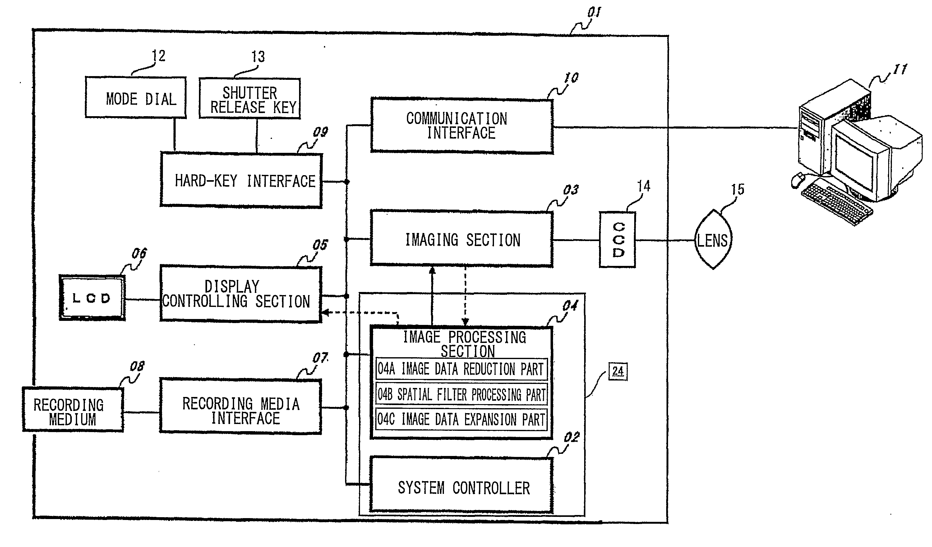
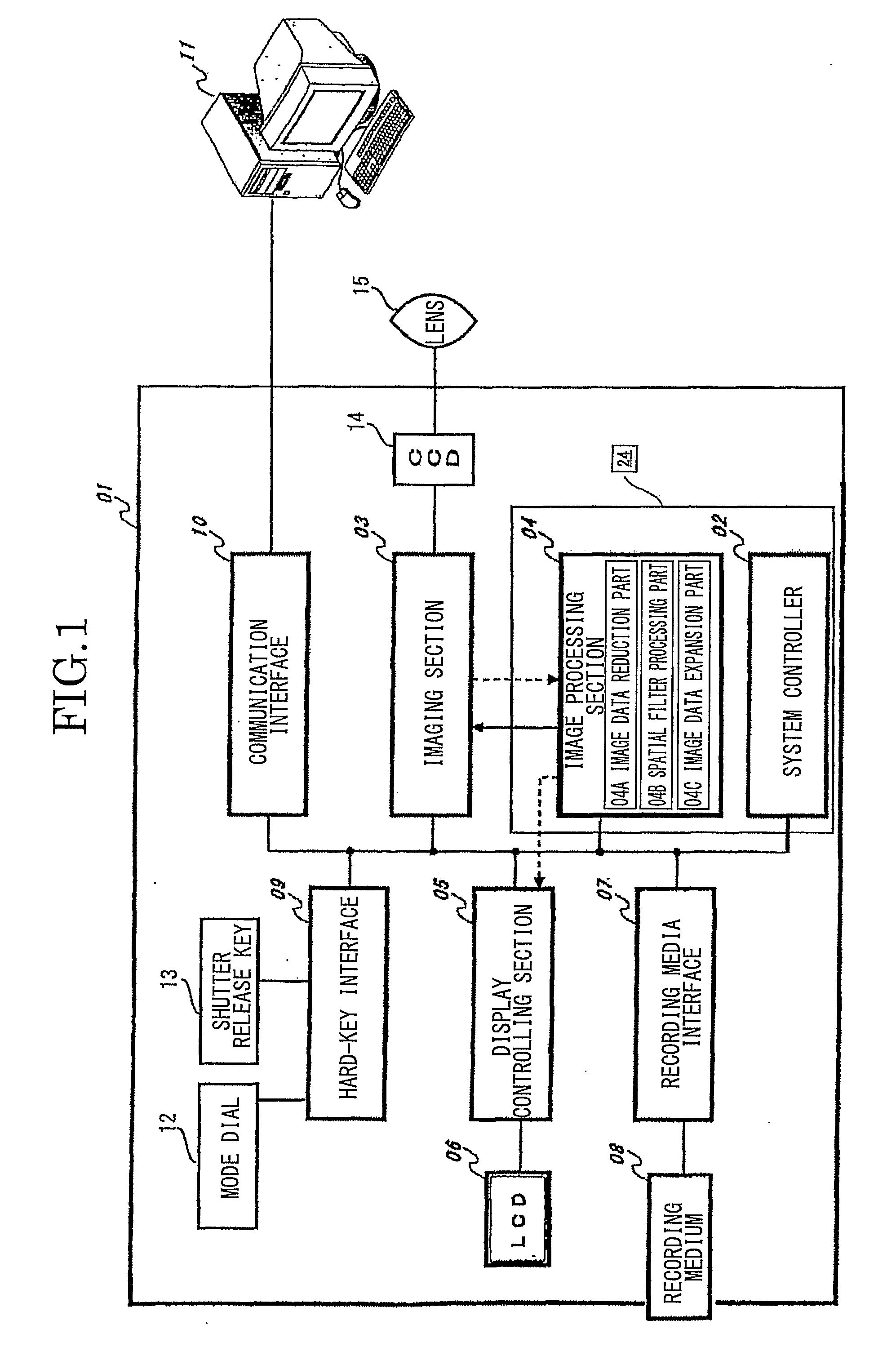
[0058]FIG. 1 schematically illustrates a structure of a digital camera and a connected device according to a first embodiment of the present invention.

[0059]Referring to FIG. 1, a digital camera 01 is illustrated. The digital camera 01 includes a system controller 02, and an imaging section 03. The system controller 02 is provided, for example, with a CPU (Central Processing Unit), a NAND flash memory, a SDRAM (Synchronous Dynamic Random Access Memory), and a timer, and is provided for controlling all parts of the digital camera 01. The imaging section 03 is provided, for example, with a motor for driving an imaging optical system, a CCD driving circuit for driving a CCD (Charge-Coupled Device) 14, and an A / D (Analog / Digital) converter.

[0060]The digital camera 01 includes an image processing section 04, which applies various image processes to an image signal obtained by the imaging section 03. The image processing section 04 is provided, for example, with an image processing DSP (D...

second embodiment

[0112]Next, a second embodiment of the present invention will be described with reference to FIGS. 11 and 12. The second embodiment obtains a photographic object distance in each region including a photographic object and a background part, and changes an amount of blurring according to the photographic object distance in each of the regions.

[0113]FIG. 11 is a flowchart illustrating a flow of operation of a digital camera according to the second embodiment of the invention. In FIG. 11, steps 02-001 to 02-007 are similar to the steps 01-001 to 01-007 of FIG. 5A, so they will not be described in detail. The image processing section 04 divides a background image into plural parts on the basis of photographic object distances (step 02-008).

[0114]FIG. 12 explains image processing of the digital camera according to the second embodiment, in which the background image is divided into several parts. Referring to FIG. 12, a photographing image 200, a main photographic object 201, an extracte...


PUM


Abstract

An image processor (24) includes an image processing section (04) which performs a blurring process on a given image data. The image processing section (04) is provided with an image data reduction part (04A), a spatial filter processing part (04B), and an image data expansion part (04C). The image data reduction part (04A) reduces the given image data at a predetermined reduction rate to generate a reduced image data. The spatial filter processing part (04B) performs a spatial filter process on the reduced image data reduced by the image data reduction part (04A) to generate a processed image data. An image data expansion part (04C) expands the processed image data processed by the spatial filter processing part (04B) at an expansion rate inverse of the reduction rate.

Description

TECHNICAL FIELD[0001]The present invention relates to an image processor, an image processing method, a digital camera, and an imaging apparatus, each having a function of performing a blurring process on an image.BACKGROUND ART[0002]Generally, an area of an imaging device used for a so-called compact digital camera is smaller than that of an imaging device used in a single-lens reflex digital camera, or is smaller than an exposure area of a silver-salt film used in a single-lens reflex camera. Thus, a focal distance of the compact digital camera is shorter than that of the single-lens reflex digital camera or the single-lens reflex camera, when the focal distances of photographic optical systems thereof necessary for photographing an image having the same angle of field are compared with each other. In addition, when an F-number of each of the photographic optical systems is set to be constant, a depth of field of the photographic optical system having the shorter focal distance be...

Claims


Application Information

Patent Timeline
IPC IPC(8): H04N5/228G06K9/54
CPCG06T3/40G06T5/20H04N5/23229H04N5/23212H04N5/232G06T2207/30196H04N2101/00G06T2207/20016H04N23/673H04N23/951H04N23/80H04N23/633G06T5/70
Inventor WATANABE, YOSHIKAZU
Owner RICOH KK
Learn More