

Interferometer, demodulator, and optical fiber communication module
a technology of interferometer and demodulator, which is applied in the direction of polarising elements, instruments, transmission monitoring, etc., can solve the problems of inability to cope with a case where the relative phase difference is not possible, complicated design, and complicated assembly adjustment of delay line interferometers, etc., to achieve stable demodulated signals, eliminate stably, and facilitate assembly adjustment of optical systems in demodulators
- Summary
- Abstract
- Description
- Claims
- Application Information
AI Technical Summary
Benefits of technology
Problems solved by technology
Method used
Image

Examples
first embodiment
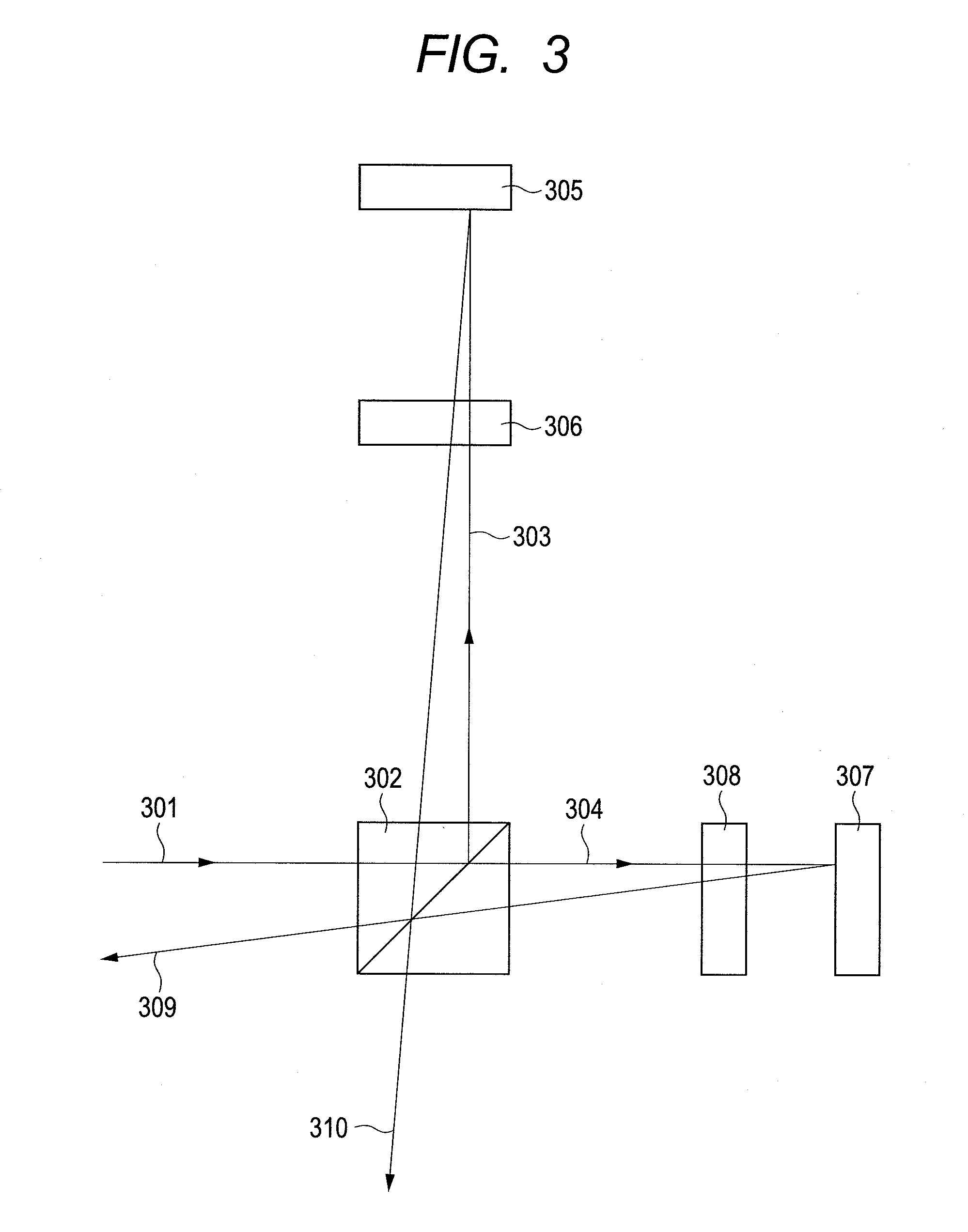
[0034]Now, with reference to FIG. 3, an embodiment of the present invention will be described.
[0035]FIG. 3 shows a fundamental embodiment of the present invention. A DSPK-modulated light 301 enters a half beam splitter 302 and is split into first split light 303 and second split light 304 with an intensity ratio of 1:1. The first split light 303 enters a mirror 305 at an angle of almost 90 degrees. The light reflected on the mirror 305 enters the beam splitter 302 again. In this regard, a quarter wave plate 306 is disposed on an optical path along which the first split light does a round trip, and its fast axis direction makes an angle of 45 degrees with respect to p polarization defined by a split surface of the half beam splitter 302. As a result, of the polarization elements of the first split light 303, a p polarization element is converted to an s polarization element when it enters the half beam splitter 302 again. In the same manner, an s polarization element is converted to ...
second embodiment
[0059]As another embodiment, FIG. 5 shows a case where an optical axis direction of the split beams of light when being split and an optical axis direction of the beams of light when being multiplied are of antiparallel to each other. In this case, in place of the mirrors 305 and 307 of the first embodiment, mirror pairs 501 and 502 are implemented, respectively. Then, the position of the split light is shifted, and the split beams of light are emitted precisely in the opposite directions. That is, an optical axis direction of the outgoing light to the mirror pair and an optical axis direction of the return light from the mirror pair are set not to be in parallel with each other. In order that the optical axis direction of the return light from the mirror pairs 501 and 502 is precisely in antiparallel with the direction of the optical axis of the incident light, two mirror surfaces which constitute the mirror pairs are orthogonal to each other. When a phase φ occurring in the half b...
third embodiment
[0060]As another embodiment, FIG. 6 shows a case where a p polarization element and an s polarization element of the split light are reversed by a group of mirrors 601 and 602. As shown in FIG. 7, the group of mirrors 601 and 602 comprises three mirrors 701, 702, and 703. With the above structure, first, the incident light 704 is reflected vertically. Then, it is reflected horizontally (namely, in a direction orthogonal to the incident light). Finally, it is reflected in the direction opposite to the direction of the incident light and then emitted as return light 705. In this regard, when the incident light is of p polarization (horizontal polarization), as shown in the polarization directions 706, 707, 708, and 709 of FIG. 7, the polarized light rotates geometrically during a process of reflection inside the mirror group. Then, when the polarized light is emitted as return light, it is converted to s polarized light (vertical polarization). Exactly in the same manner, when the inc...
PUM
 Abstract
Description
Claims
Application Information