Solar module

Inactive Publication Date: 2011-01-06
FRAUNHOFER GESELLSCHAFT ZUR FOERDERUNG DER ANGEWANDTEN FORSCHUNG EV
View PDF23 Cites 18 Cited by
  • Summary
  • Abstract
  • Description
  • Claims
  • Application Information

AI Technical Summary

Benefits of technology

[0022]The invention is solar modules having higher mechanical stability, in particular higher bending stiffness and bending strength, so that, for example, a module of this construction having an area of approximately 1.40 m2, can without further additional supports, such as aluminum frames, aluminum struts, a stable support construction, which prevents sagging of the module under load, only supports itself while withstanding all mechanical load tests prescribed in the relevant standards, based on photoactive elements. The solar module is particularly cost-effective, robust in relation to external influences, has a long lifetime, and ensures high efficiency even in the case of high sunlight temperatures.

Problems solved by technology

Key factors for cost-effective generation of solar current are the production costs and the durability of the solar modules.
Embedding of this type is not capable of transmitting mechanical strain which is an aspect that is discussed in greater detail hereafter.
The encapsulation or embedding materials used must have good barrier properties against water vapor and oxygen, in particular because corrosion-related damage arises on metal contacts due to water vapor or oxygen and degradation of the EVA material occurs.
High material and manufacturing costs, caused by: special front glass, special composite films for the rear side, vacuum lamination, aluminum frame, the required mechanical work, such as soldering of the electrical lines, installation and contacting of the sockets, and the relatively long processing times for the lamination and cross-linking of the EVA, result in a comparatively high proportion of the costs for the modular construction of the total costs which are in the double-digit percentage range.
In addition, conventional solar modules have a high weight due to the relatively thick front glass pane, which in turn requires stable and costly retaining structures.
In full sunlight, the modules heat up to 80° C., which results in a reduction of the efficiency of the solar cells.
However, these proposals are also not properly rewarding.
The photovoltaic panel comprises a combination of a layer made of transparent material, a configuration of interconnected photovoltaic cells, and a rear side layer, which does not offer any mechanical stability.
This results in only slight bending stiffness of the entire solar module.
Both cases result in a high weight of the module.
This configuration results in high module weights for large-area, robust solar modules, which are provided for the purpose of solar powered energy sources having typical area sizes of at least one square meter and / or for roof installation on buildings.
These solar modules may be implemented as stiff and simultaneously light due to the hollow chamber structure of the rear side construction, but the rear side construction must be implemented as very thick for this purpose, which is connected to significant heat buildup and has a negative effect on the efficiency.
The heat dissipation is only possible in the case of these elements if the hollow chambers of the rear side construction are intentionally used for the heat dissipation, which however typically cannot be implemented in the case of modules provided for roof installation on buildings.

Method used


Image

  • Solar module
  • Solar module

Examples


Embodiment Construction

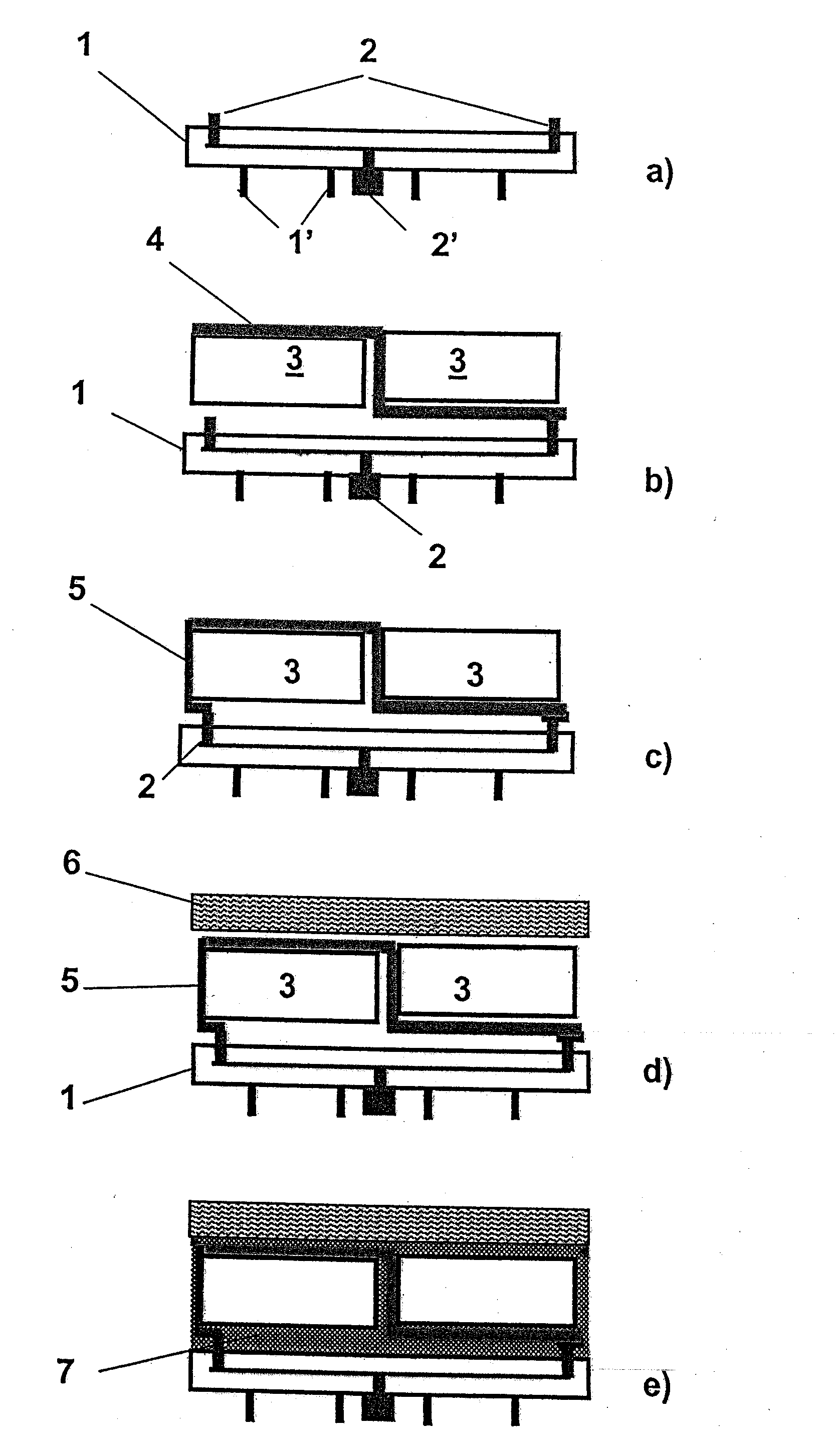
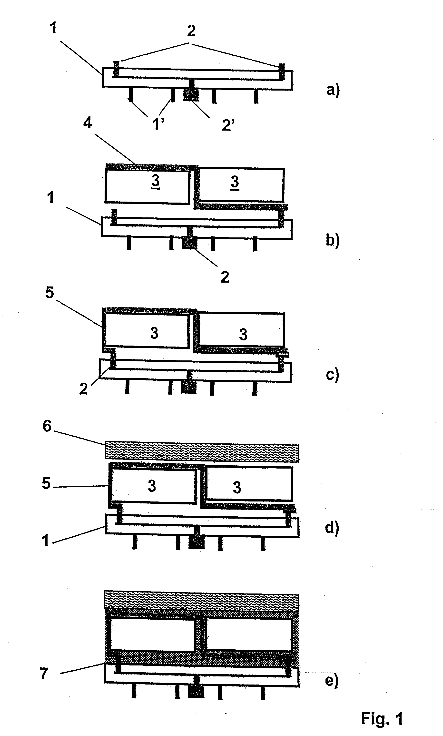
[0056]Manufacturing steps for the cost-effective production of a solar module are shown in FIGS. 1a through e.

[0057]A plastic carrier 1 is shown as a rear side construction in FIG. 1a, which is produced from a plastic material in the course of an injection molding or injection-compression molding method or in the course of a compression method. In addition, an electrical terminal structure 2 for the later electrical contacting of the solar cell configuration is provided within the plastic carrier 1. The electrical terminal structure 2 is advantageously implemented as stiff at least in the sections in which it is completely enveloped by the plastic material of the plastic carrier 1, for example, by profiling as rails. The plastic carrier experiences improved surface stiffness through the embedded electrical terminal structure 2. In addition, the plastic carrier 1 has ribbed struts 1′ on its rear side, which are used, on the one hand, for further stabilization and also for fastening ...


PUM


Abstract

A solar module is described having a flatly implemented solar cell configuration, on whose rear side a rear side construction is provided and on whose front side a radiation-transparent front pane is provided, having a solidifying grouting compound, which encloses the solar cell configuration between rear side construction and front pane and transmits mechanical loads, and which connects the surface of the front pane facing toward the rear side construction over its entire area to the rear side construction and completely encloses the solar cell configuration. The rear side construction is implemented as a separate module, which is a plastic carrier produced using injection molding, injection-compression molding, or compression, or in the form of a stiff ceramic or organic planar element.

Description

BACKGROUND OF THE INVENTION[0001]1. Field of the Invention[0002]The invention relates to a solar module having a flatly implemented solar cell configuration, on whose rear side a rear side construction is provided and on whose front side a radiation-transparent front pane is provided, having a grouting compound, which encloses the solar cell configuration between the rear side construction and front pane, is capable of solidifying, and transmits mechanical loads, and which connects the surface of the front pane facing toward the rear side construction over its entire area to the rear side construction and completely encloses the solar cell configuration.[0003]2. Description of the Prior Art[0004]Solar modules are photovoltaic components for direct generation of electrical current from sunlight. Key factors for cost-effective generation of solar current are the production costs and the durability of the solar modules.[0005]Solar modules typically comprise a composite made of a front ...

Claims


Application Information

Patent Timeline
IPC IPC(8): H01L31/055
CPCH01L31/048Y02E10/52H01L31/0508H01L31/055
Inventor BUSCH, MICHAELBAGDAHN, JORG
Owner FRAUNHOFER GESELLSCHAFT ZUR FOERDERUNG DER ANGEWANDTEN FORSCHUNG EV
Why Eureka
Try Eureka