Electrical patterns for biosensor and method of making

a biosensor and electric pattern technology, applied in the field of electrochemical biosensors, can solve the problems of undesired time-consuming techniques, and achieve the effect of great precision and detail

Active Publication Date: 2011-01-06
ROCHE DIABETES CARE INC
View PDF35 Cites 9 Cited by
  • Summary
  • Abstract
  • Description
  • Claims
  • Application Information

AI Technical Summary

Benefits of technology

[0016]In one exemplary embodiment, the depositing step comprises depositing a layer of the first electrically conductive material on the portion of the base material and depositing a second layer of the second electrically conductive material on the portion of the base material substantially side by side to and in electrical contact with the first layer. In one exemplary production method, this layered portion of base material can be rolled onto a supply roll and provided as a “production-ready” material to a manufacturing process. This material is then unrolled and portions of the first and second layers are removed to form the electrical p

Problems solved by technology

The scribing is accomplished by moving the laser beam across the surface to be ablated, and such a tech

Method used


Image

  • Electrical patterns for biosensor and method of making
  • Electrical patterns for biosensor and method of making
  • Electrical patterns for biosensor and method of making

Examples


Embodiment Construction

[0034]The embodiments of the present invention described below are not intended to be exhaustive or to limit the invention to the precise forms disclosed in the following detailed description. Rather, the embodiments are chosen and described so that others skilled in the art may appreciate and understand the principles and practices of the present invention.

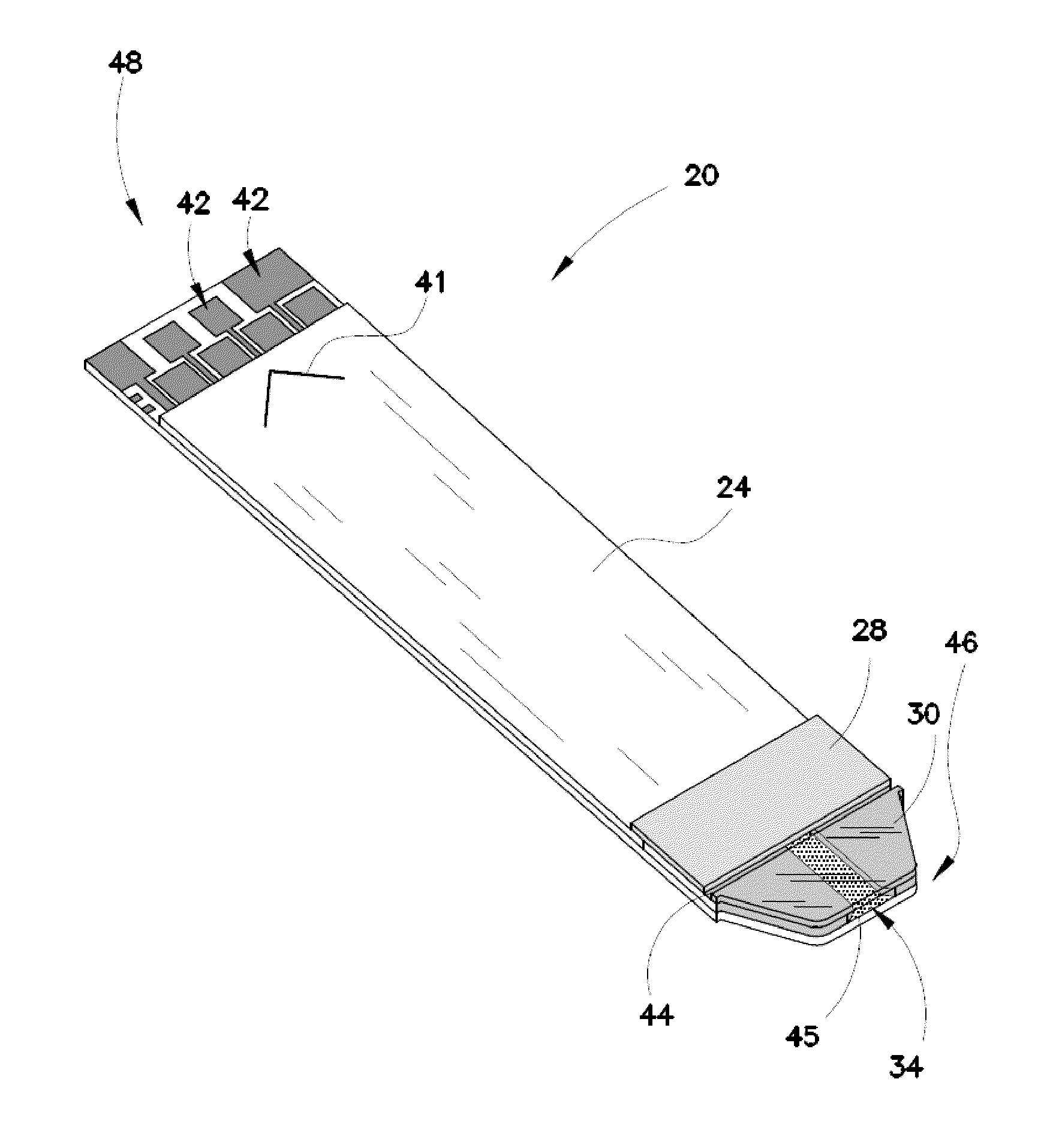
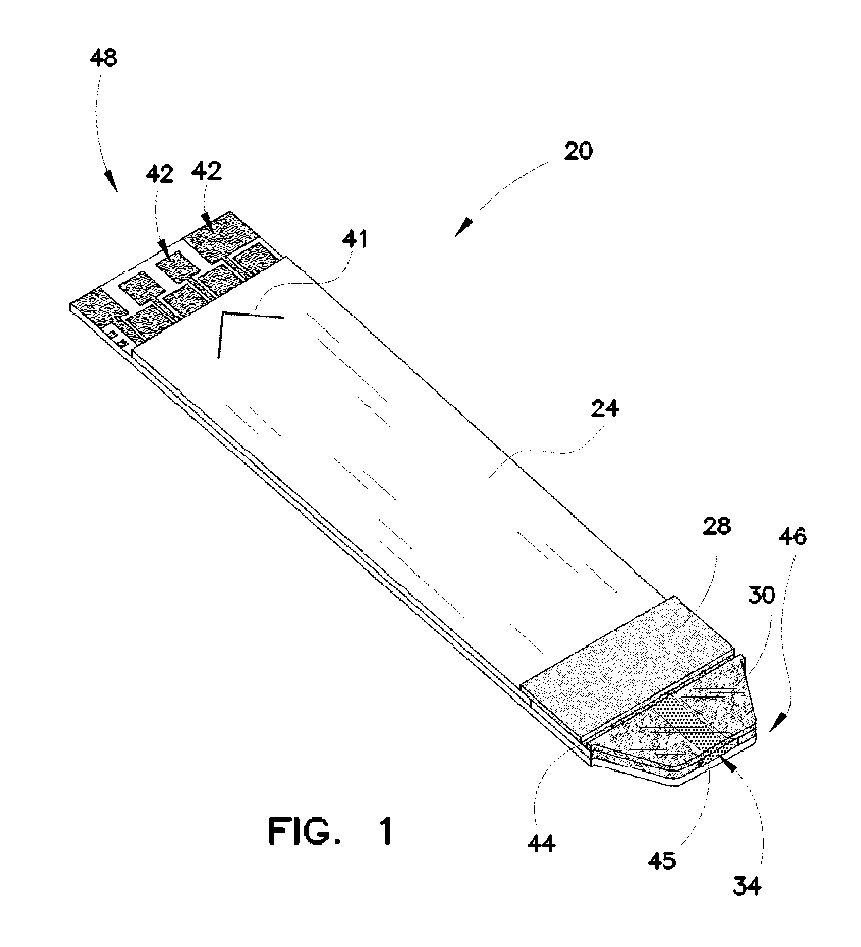
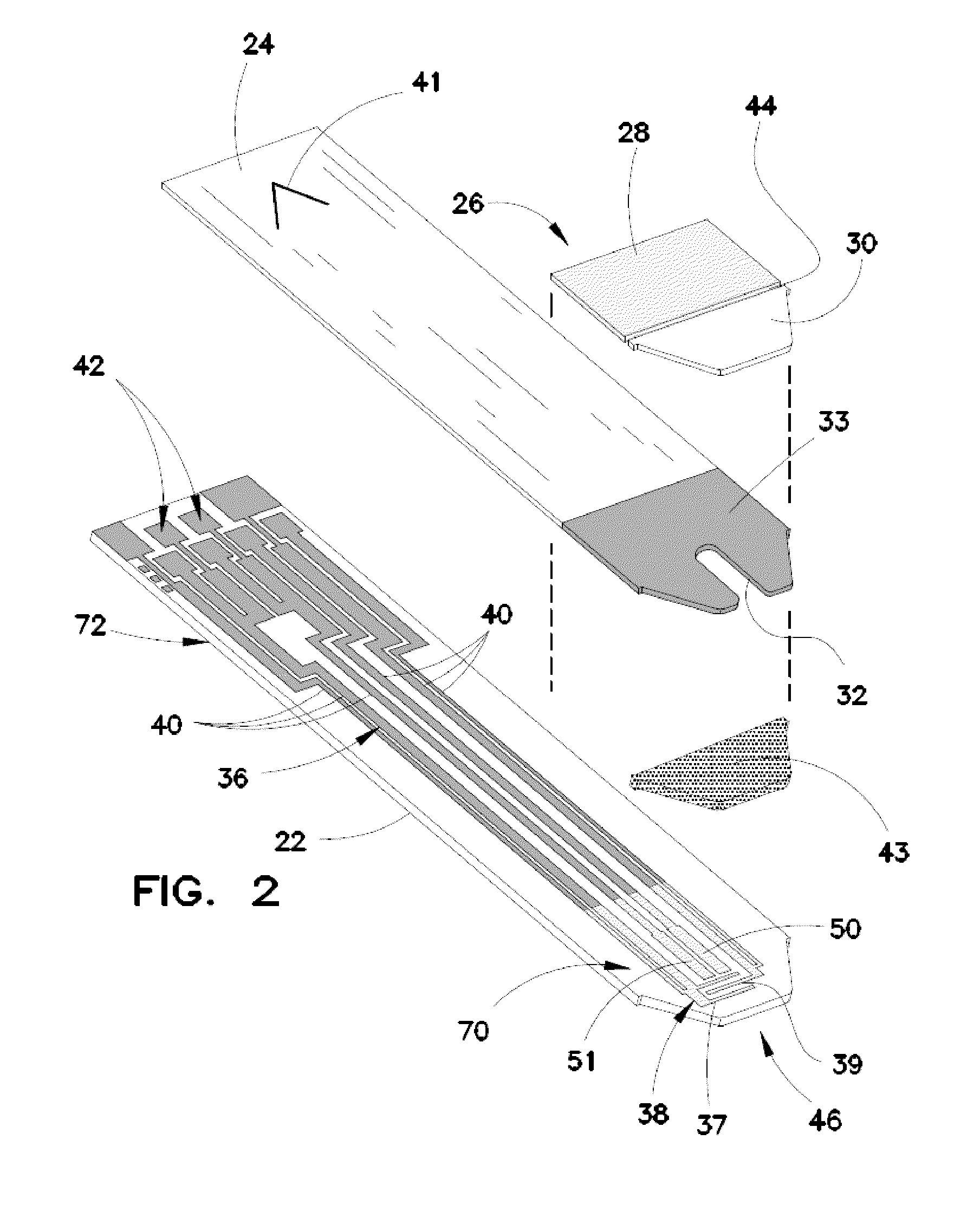
[0035]Turning now to FIGS. 1 and 2, there is shown an embodiment of a biosensor useful in accordance with the present teachings. Biosensor 20 includes a base substrate 22, a spacing layer 24 and a covering layer comprising body cover 28 and chamber cover 30. The spacing layer 24 includes a void portion 32 to provide a sample-receiving chamber 34 extending between the base substrate 22 and the covering layer. An alternative covering layer could comprise a top cover (not shown) overlying the spacing layer 24 and including a vent hole (not shown) in fluid communication with the sample-receiving chamber 34.

[0036]The base substrate 22...


PUM

PropertyMeasurementUnit
Electrical conductivityaaaaaaaaaa
Lengthaaaaaaaaaa
Widthaaaaaaaaaa

Abstract

The present invention provides an inventive biosensor that includes multiple regions in which the electrical pattern is formed from different electrically conductive materials. The present invention also provides an inventive method for mass producing biosensors as just described. In one embodiment of this method, first and second different electrically conductive materials are deposited side by side on a portion of an electrically insulating base material, and a plurality of electrical patterns is formed on the portion of the base material. Each electrical pattern includes a first region formed from the first electrically conductive material electrically connected to a second region formed from the second electrically conductive material. The electrically conductive materials can be deposited as layers on the base material and portions of the layers can be removed to form the electrical patterns, or, the electrical patterns can be formed by transferring the conductive material in the shape of the electrical pattern directly to the base material, such as by a laser direct transfer technique.

Description

RELATED APPLICATIONS[0001]This application is a continuation of International Patent Application Number PCT / EP2008 / 009143 filed on Oct. 29, 2008, which claims the benefit of U.S. Patent Application Ser. No. 60 / 984,279 filed on Oct. 31, 2007, both of which are incorporated herein by reference in their entireties.FIELD OF THE INVENTION[0002]The present invention relates generally to the testing of body fluids for concentration of analytes and more particularly to an electrochemical biosensor for such testing and a method of making the same.BACKGROUND[0003]Test strips or biosensors are often used to measure the presence and / or concentrations of selected analytes in fluid test samples. For example, a variety of test strips are used to measure glucose concentrations in blood to monitor the blood sugar level of people with diabetes. These test strips include a reaction chamber into which a reagent composition has been deposited. Current trends in test strips require smaller test samples a...

Claims


Application Information

Patent Timeline
IPC IPC(8): B32B38/04G01N27/26C23C28/00C23C16/00B05D3/06C23C14/34B05D5/12B29C35/08
CPCG01N33/5438Y10T29/49155Y10T29/49156Y10T156/1082Y10T29/49117G01N27/3277G01N27/3272
Inventor BHULLAR, RAGHBIR SINGHCELENATANO, MIKEEL-RAHAIBY, SAID K.
Owner ROCHE DIABETES CARE INC
Why Eureka
Try Eureka