Form printing system, control method and computer-readable medium

a control method and form printing technology, applied in the field of form printing system, can solve the problem of long time occupied by the printing device, and achieve the effect of curtailing the amount of time for which the printing device is occupied by the user, reducing the possibility of information in the encoded code being easily leaked, and reducing the possibility of leaking information

Inactive Publication Date: 2011-01-06
CANON KK
View PDF3 Cites 12 Cited by
  • Summary
  • Abstract
  • Description
  • Claims
  • Application Information

AI Technical Summary

Benefits of technology

[0009]According to the present invention, it is no longer necessary to save and manage print data for executing printing on a print server, a host computer or the like beforehand. The amount of time for which the printing device is occupied by a user can be curtailed as a result of a print instruction been given by reading an encoded code. Also, since form information and field data are encrypted with the device identification information of the mobile terminal and encoded to obtain an encoded code, the possibility of information in the encoded code being easily leaked is eliminated, even in the case where the encoded code is read by a malicious third party.
[0010]According to the present invention, management processing and necessary resources relating to saving print data can be curtailed. Occupation of the printing device by a specific user can also be curtailed. Further, security aspects can also be improved, since information unique to the apparatus used by the user is used in authentication.

Problems solved by technology

Also, in the case where user authentication is performed from a control panel of a printing apparatus, the device is occupied for a long time in order to input user authentication information.
Further, in the case where data for printing is embedded in an encoded code, the encoded code could possibly be read by a malicious third party and information leaked.

Method used


Image

  • Form printing system, control method and computer-readable medium
  • Form printing system, control method and computer-readable medium
  • Form printing system, control method and computer-readable medium

Examples


first embodiment

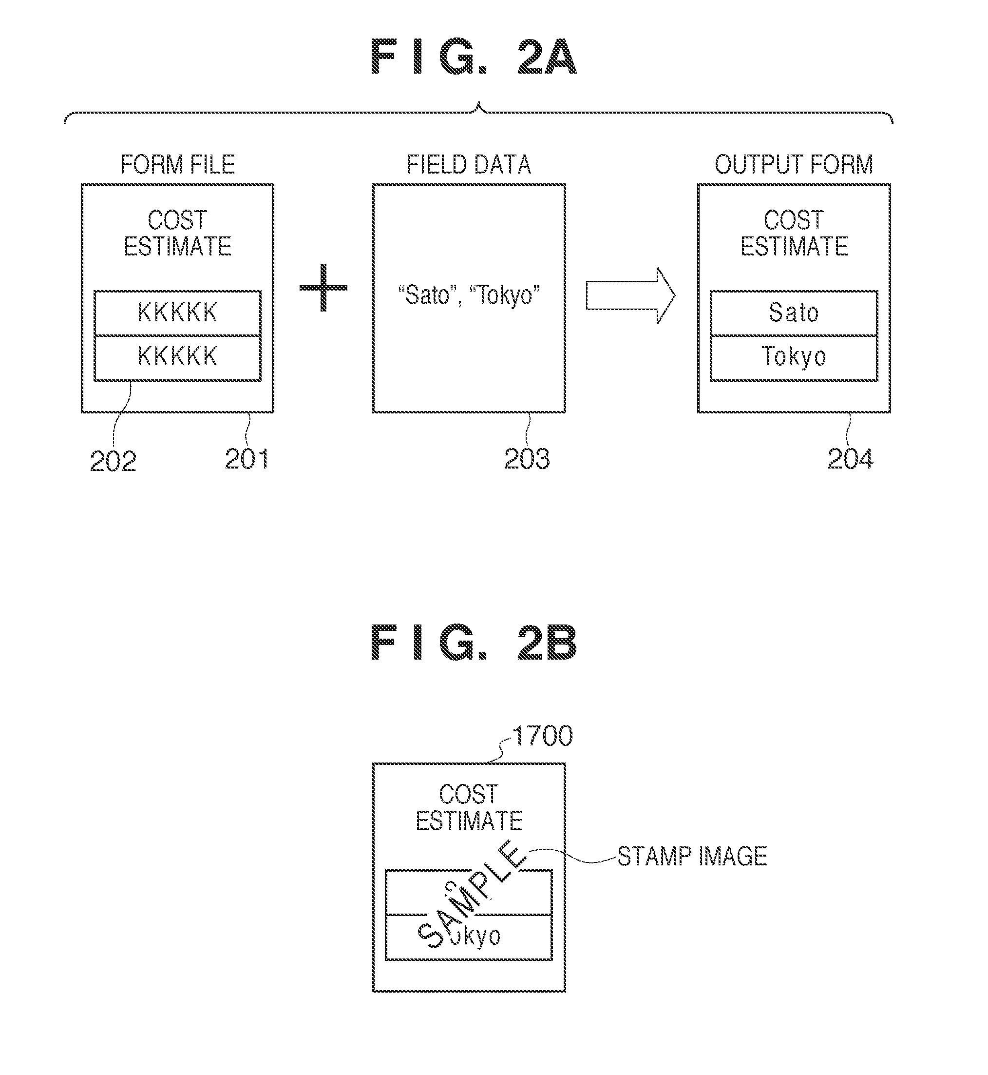
[0027]Firstly, the premise of the present invention will be described. When overlay outputting a form, the data of a data file 203 is incorporated into prescribed locations 202 (fields) of a form file 201 indicating a layout of the form to obtain an output form 204, as shown in FIG. 2A. Hereinafter, graphics 202 indicating the locations (fields) into which data is incorporated will be called field graphics, and the data file 203 will be called field data.

[0028]System Configuration

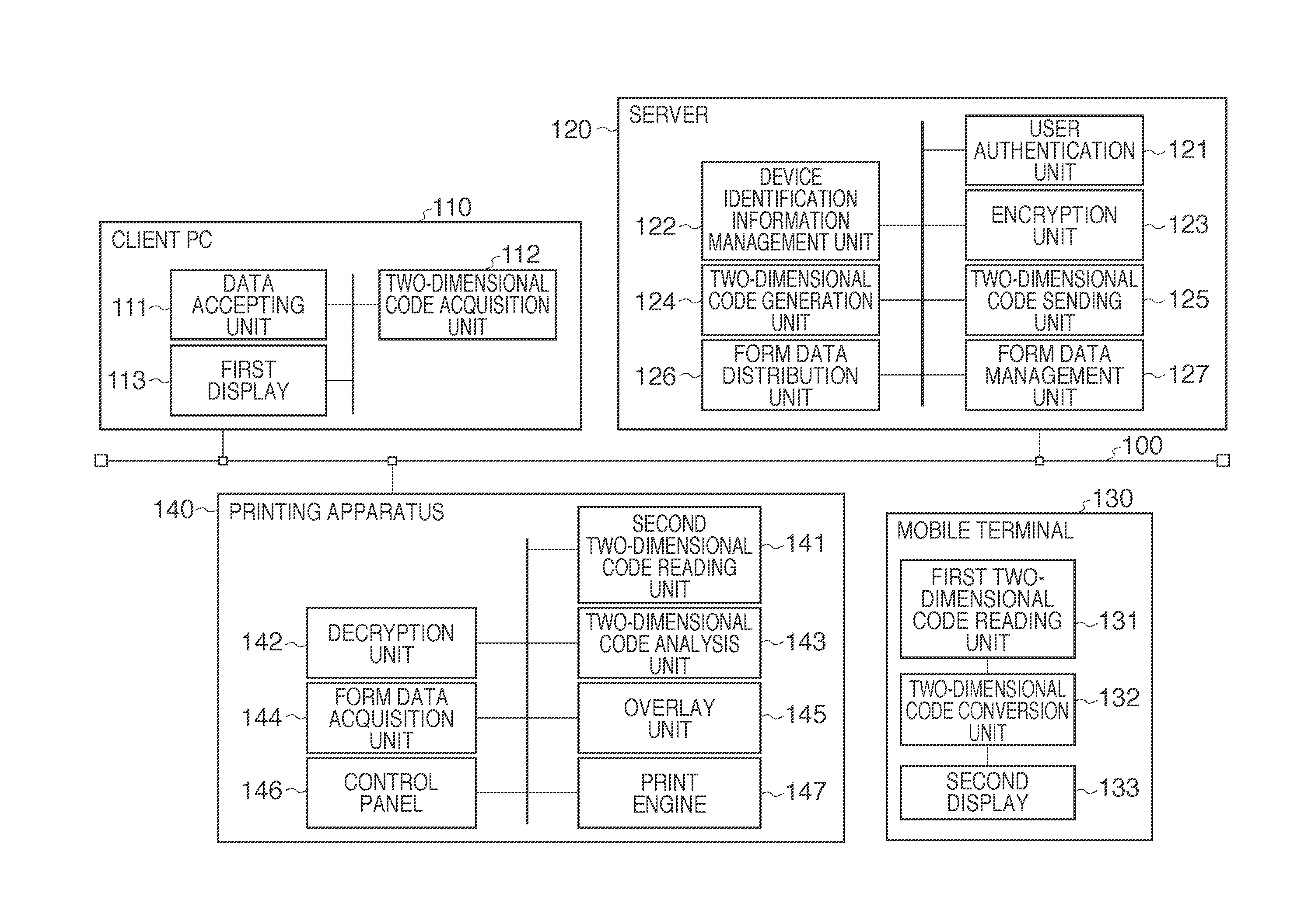
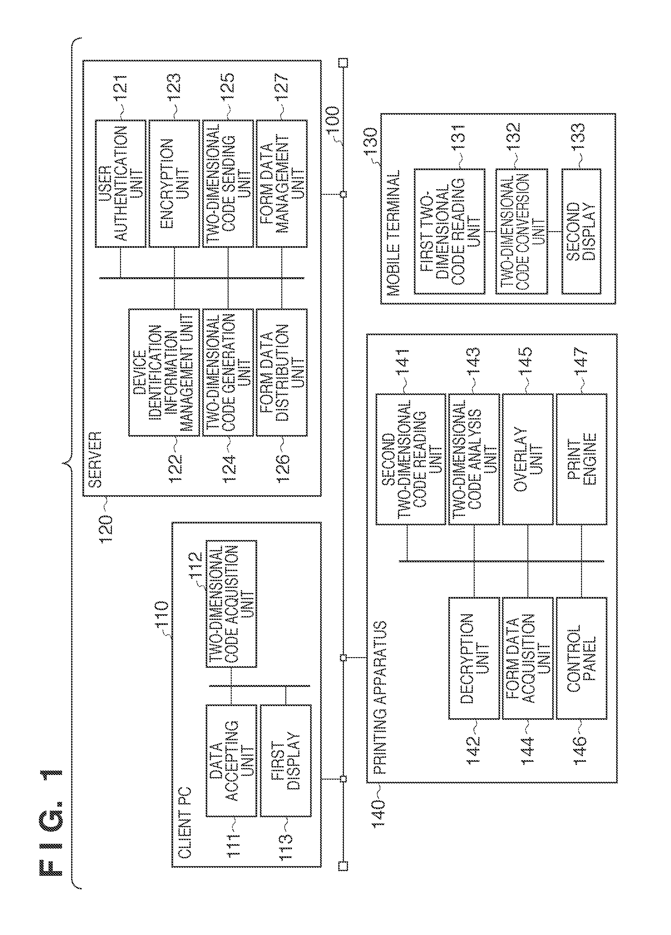
[0029]Next, embodiments for implementing the present invention will be described using the drawings. FIG. 1 is a block diagram showing an example configuration of a form printing system according to the embodiments of the present invention. As shown in FIG. 1, this form printing system is constituted by a client PC 110, which is an information processing apparatus, a server 120, a mobile terminal 130, and a printing apparatus 140 that are connected to a network 100. The mobile terminal 130 holds device iden...

second embodiment

[0047]In the First Embodiment, the case was described where form printing is performed after the mobile terminal 130 has added the device identification information of the mobile terminal 130 to create a second two-dimensional code. In the present embodiment, a variation of output when form printing is performed in cases such as where there is no mobile terminal 130 (e.g., where the first two-dimensional code is read with a digital camera), or where printing is performed to a paper medium and the first two-dimensional code is read from the paper medium to the printing apparatus 140 will be described. Note that since the first two-dimensional code generation process in the case of the present embodiment is similar to the First Embodiment, description thereof will be omitted.

[0048]Overlay Printing Process

[0049]FIG. 8 is a flowchart showing the overlay printing process according to the Second Embodiment. FIG. 9A shows example screen of a user authentication input screen 1000 serving as...

third embodiment

[0052]With the abovementioned First Embodiment and Second Embodiment, printing using created first and second two-dimensional codes, which are encoded codes, can be performed without restriction any number of times provided that user authentication is performed normally. However, it may be desirable to restrict the number of times a form is printed if the form is a confidential document or the like. In the present embodiment, the case where the number of times printing is performed in the form printing system is controlled will be described. FIG. 10 is an example block diagram of the server 120 according to the present embodiment. In contrast to the First and Second Embodiments, an encoded code ID that uniquely identifies the first two-dimensional code (referred to here as a “two-dimensional code ID” for convenience sake) is used. Thus, a two-dimensional code ID generation unit 128 that generates a two-dimensional code ID, and a print number management unit 129 that manages the two-...


PUM


Abstract

A form printing system comprising an information processing apparatus, a server, and a printing apparatus that are connected to each other, wherein the server includes: a device identification information management unit that manages device identification information in association with user-specific user authentication information; an encryption unit that encrypts the field data and the form information received from the information processing apparatus; an encoded code generation unit that generates the first encoded code from an encrypted character string generated by the encryption unit; an encoded code sending unit that sends the first encoded code generated by the encoded code generation unit to the information processing apparatus; a form data distribution unit that, in a case where a form data acquisition request that includes form information is received from the printing apparatus, sends form data that is in accordance with the acquisition request to the printing apparatus.

Description

BACKGROUND OF THE INVENTION[0001]1. Field of the Invention[0002]The present invention relates to a form printing system, a control method and a storage medium. More particularly, the present invention relates to a mechanism for overlay printing using a printing apparatus shared on a network.[0003]2. Description of the Related Art[0004]A technique called form overlay is used in order to create printed material that is created by writing data onto a prescribed form such as a ledger sheet. With form overlay, form data representing the form portion is created in advance, data such as numerical values or character strings called field data is overlaid in prescribed places of the form data, and the generated data is printed or displayed.[0005]In another print system, print data is sent to a printer with a host computer acting as an initiator, and printing is executed by the printer. In contrast, there is a print system called a pull print system. With a pull print system, when print data ...

Claims


Application Information

Patent Timeline
Patent Type & Authority Applications(United States)
IPC IPC(8): G06K15/02
CPCG06F21/608
Inventor SATO, YUICHIRO
Owner CANON KK
Why Eureka
Try Eureka