Reactor plate and reaction processing method

a technology of reaction product and reactor plate, which is applied in the field of reactor plate, can solve the problems of reaction product leakage through the port, foreign matter entering, and polluting the surrounding environment, so as to prevent the pollution of the environment, increase the introduction pressure applied, and inject liquid smoothly

Active Publication Date: 2011-01-06
SHIMADZU CORP
View PDF15 Cites 27 Cited by
  • Summary
  • Abstract
  • Description
  • Claims
  • Application Information

AI Technical Summary

Benefits of technology

[0026]As described above, since the reaction processing method according to the present invention is carried out using the reactor plate according to the present invention including a reaction well, a reaction well channel connected to the reaction well, and a reaction well air vent channel connected to the reaction well, wherein the reaction well channel is constituted from a groove formed in the contact surface between two members bonded together or from the groove and a through hole formed in the member and includes a main channel, a metering channel branched off the main channel and having a predetermined capacity, and an injection channel whose one end is connected to the metering channel and the other end is connected to the reaction well, and wherein the main channel and the reaction well air vent channel are hermetically sealed and the injection channel is formed narrower than the metering channel and does not allow the passage of a liquid at an introduction pressure applied to introduce the liquid into the main channel and the metering channel and at a purge pressure applied to purge the liquid from the main channel but allows the passage of the liquid at a pressure higher than the introduction pressure and the purge pressure, it is possible to prevent the entry of foreign matter from the outside of the reactor plate and the pollution of a surrounding environment with the liquid.
[0027]Further, since the reactor plate according to the present invention has the reaction well air vent channel connected to the reaction well, it is possible to move a gas between the reaction well and the reaction well air vent channel when a liquid is injected into the reaction well through the injection channel, thereby making it possible to smoothly inject the liquid into the reaction well. The reaction well air vent channel can also be used to suck a gas contained in the reaction well to decompress the reaction well to inject a liquid into the reaction well.
[0028]In a case where the reactor plate according to the present invention is intended to be used for measuring a gene-containing sample, the sample injected into the reactor plate and then introduced into the reaction well can be processed in a closed system, and therefore it is possible to prevent the pollution of an environment outside the reactor plate and the pollution of the sample with foreign matter from outside the reactor plate.
[0029]In the channel configuration described above as an example of a channel configuration, the contact angle of each of the metering channel and the injection channel with a water droplet is preferably 90° or larger, and the area of an interface between the injection channel and the metering channel is preferably 1 to 10,000,000 μm2. This makes it difficult for a liquid to enter the injection channel when the liquid is introduced into the main channel and the metering channel, thereby making it possible to increase an introduction pressure applied to introduce the liquid into the main channel and the metering channel.
[0030]The reactor plate according to the present invention may include the plurality of reaction wells. In this case, by providing the metering channel and the injection channel for each of the reaction wells and connecting the plurality of metering channels to the main channel, it is possible to introduce a liquid into the plurality of metering channels one after another and then simultaneously inject the liquid into the plurality of reaction wells through the injection channels.
[0031]A projecting portion may be provided so as to project from a top inner surface of the reaction well. In this case, the other end of the injection channel is located at the tip of the projecting portion. By allowing the projecting portion to have a proximal end and a distal end narrower than the proximal end, a liquid to be injected into the reaction well through the injection channel can be easily dropped into the reaction well.

Problems solved by technology

Therefore, there is a possibility that foreign matter will enter a sample from outside or, on the other hand, a reaction product will pollute a surrounding environment.
However, these ports are open to the atmosphere, and therefore there is a possibility that a reaction product will leak through the ports and then pollute a surrounding environment.

Method used


Image

  • Reactor plate and reaction processing method
  • Reactor plate and reaction processing method
  • Reactor plate and reaction processing method

Examples


Embodiment Construction

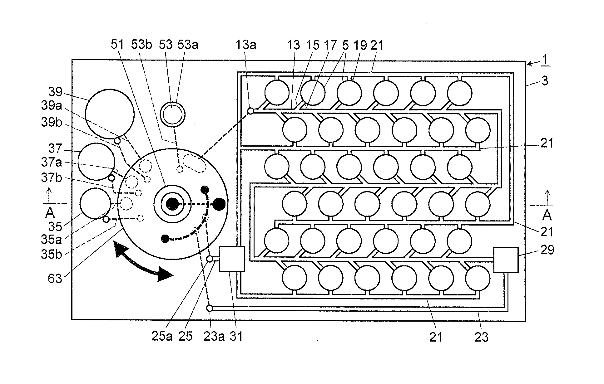
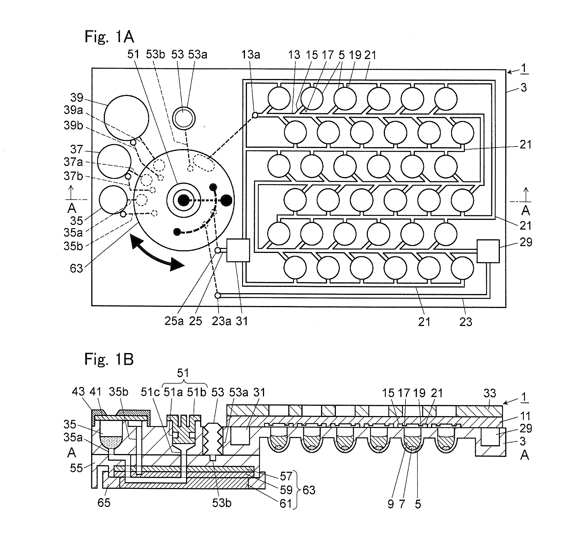
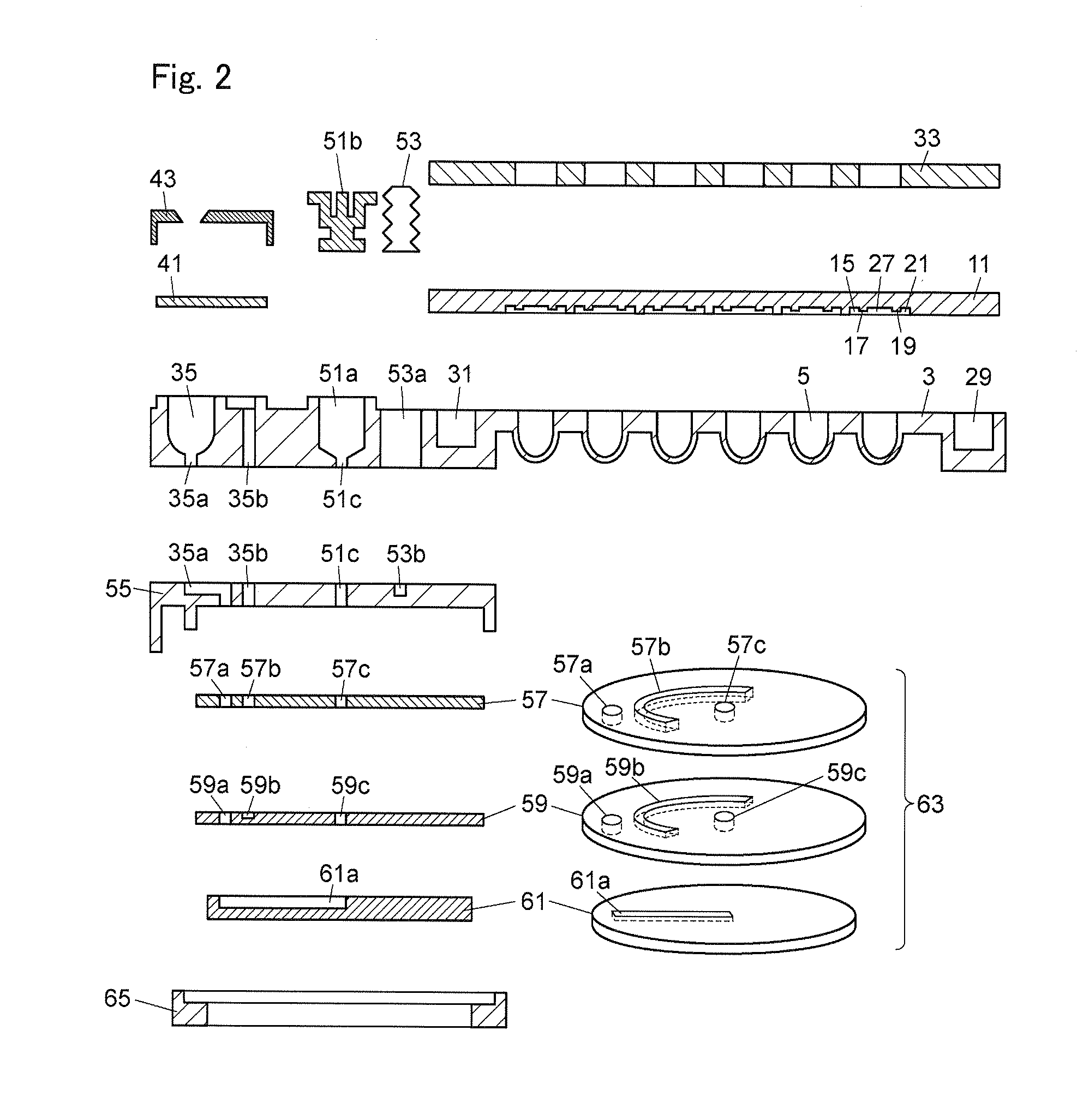
[0080]FIG. 1A is a schematic plan view of one embodiment of a reactor plate according to the present invention, and FIG. 1B is a schematic sectional view taken along the A-A line in FIG. 1A, which further includes the sectional views of a metering channel 15, an injection channel 17, reaction well air vent channels 19 and 21, a liquid drain space 29, an air drain space 31, and a bellows 53. FIG. 2 shows an exploded sectional view of the reactor plate in the embodiment shown in FIG. 1A and a schematic exploded perspective view of a switching valve. FIGS. 3A to 3C are schematic plan view, schematic perspective view, and schematic sectional view of one reaction well of the reactor plate in the embodiment shown in FIG. 1A and its vicinity, respectively. FIG. 4A is an expanded plan view of a sample well, and FIG. 4B is a sectional view taken along the B-B line in FIG. 4A. FIG. 5A is an expanded plan view of a reagent well, and FIG. 5B is a sectional view taken along the C-C line in FIG. ...


PUM

PropertyMeasurementUnit
contact angleaaaaaaaaaa
areaaaaaaaaaaa
thicknessaaaaaaaaaa

Abstract

Disclosed herein is a reactor plate which prevents the entry of foreign matter from the outside and the pollution of a surrounding environment. A reactor plate (1) includes a reaction well (5), a reaction well channel connected to the reaction well (5), and reaction well air vent channels (19) and (21) connected to the reaction well (5). The reaction well channel has a main channel (13), a metering channel (15) branched off the main channel (13), and an injection channel (17) of which one end is connected to the metering channel (15) and the other end is connected to the reaction well (5). The main channel (13) and the reaction well air vent channel (21) can be hermetically sealed. The injection channel (17) is formed narrower than the metering channel (15) not so as to allow the passage of a liquid at a liquid introduction pressure applied to introduce the liquid into the main channel (13) and the metering channel (15) and at a purge pressure applied to purge the liquid from the main channel (13) but so as to allow the passage of the liquid at a pressure higher than the liquid introduction pressure and the purge pressure.

Description

BACKGROUND OF THE INVENTION[0001]1. Field of the Invention[0002]The present invention relates to a reactor plate suitable for use in various assays and analyses such as biological and biochemical assays and general chemical analyses in the fields of medical care and chemistry, and a reaction processing method for processing such a reactor plate.[0003]2. Description of the Related Art[0004]As small reactors for use in biochemical assays or general chemical analyses, micro multi-chamber devices are used. Examples of such devices include micro well reactor plates such as a microtiter plate constituted from a plate-shaped substrate having a plurality of wells formed in the surface thereof (see, for example, Japanese Patent Application Laid-open No. 2005-177749) and the like.[0005]Further, as a structure for dispensing a small amount of liquid which can quantitatively treat a small amount of liquid, a structure having a first channel, a second channel, a third channel which is in communi...

Claims


Application Information

Patent Timeline
Patent Type & Authority Applications(United States)
IPC IPC(8): C12Q1/68C12M1/00C12M1/34
CPCB01L3/5025B01L3/502723B01L3/502738B01L3/50853B01L2200/0684B01L2200/141G01N35/1097B01L2300/0816B01L2300/0829B01L2300/0864B01L2400/0622B01L2400/0644B01L2300/046
Inventor HANAFUSA, NOBUHIROOGATA, KORETSUGUNISHIMOTO, TAKAHIROKANAI, MASAKI
Owner SHIMADZU CORP
Why Eureka
Try Eureka