Method to quantify discrete pore shapes, volumes, and surface areas using confocal profilometry

a confocal profilometry and discrete pore shape technology, applied in the field of methods for characterizing a sample of porous media, can solve the problems of not being able to disclose porous media, micp is not useful in some pore throats, and confocal microscopy is not commonly used in earth scien

Active Publication Date: 2011-01-06
SCHLUMBERGER TECH CORP
View PDF98 Cites 45 Cited by
  • Summary
  • Abstract
  • Description
  • Claims
  • Application Information

AI Technical Summary

Benefits of technology

[0041]Another advantage of at least one embodiment of the invention is that the invention is capable of using the digital images obtained by confocal profilometry for directly using them as training images. Wherein, an MPS (Filtersim algorithm) can then be used to generate different 2D realizations of carbonate rock textures (vuggy porosity) for reconstructing vug distributions in 3D. Moreover, this can allow for the quantitative evaluation of 3D pore-size distributions using 2D digital images by confocal profilometry scanning of rock samples.
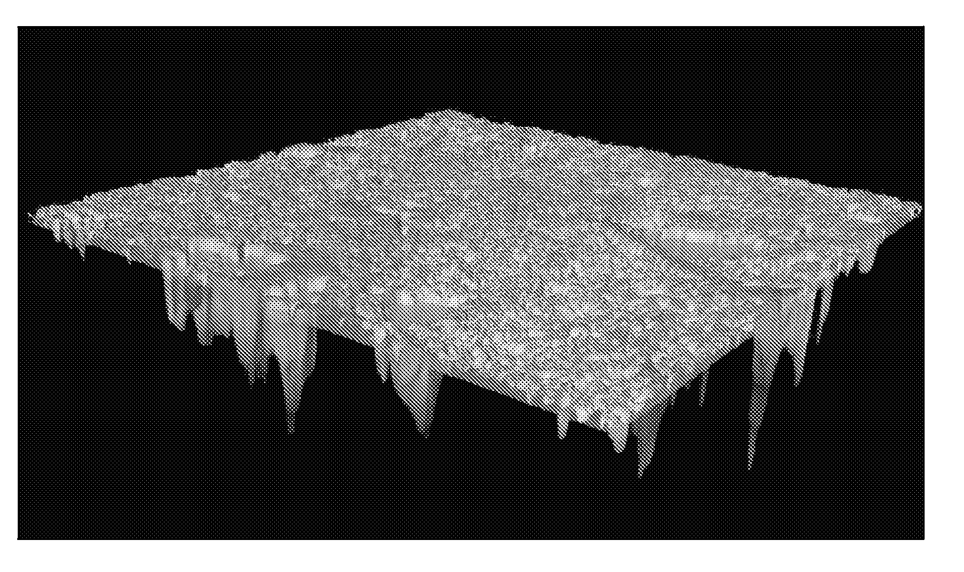
[0042]Another advantage of at least one embodiment of the invention is that the invention is capable of using non-contacting white-light and laser confocal profilometry as a method to quantify discrete pore shapes, volumes, and surface areas in porous media.

Problems solved by technology

Further, it is noted confocal microscopy is not commonly used in the earth sciences.
MICP is not useful for some pore throats because these throats are filled at very low injection pressures.
An issue raised implicitly by current MPS algorithms is how to generate training images.
Further still, U.S. Pat. No. 6,750,974 discusses 3D imaging of droplets, however it does not disclose porous media.

Method used


Image

  • Method to quantify discrete pore shapes, volumes, and surface areas using confocal profilometry
  • Method to quantify discrete pore shapes, volumes, and surface areas using confocal profilometry
  • Method to quantify discrete pore shapes, volumes, and surface areas using confocal profilometry

Examples


examples

Laser Confocal Profilometry

[0101]Referring to FIGS. 22-24, it is noted FIGS. 22 and 23 show scanned views of a polished rock surface, with mineral grains and open pores. It is noted FIG. 22 shows a dolomite imaged using confocal reflected laser microscopy, wherein the black is open porosity, gray is the dolomite mineral and having an objective 20×, scanned area 616×462μ. FIG. 23 shows a pore bodies (total 1921) for entire image from confocal reflected laser profilometry, wherein the Objective is 20× and the area is 616×462μ. The laser confocal scan is saved as a .txt file and loaded into 3D visualization software following Parts [1] through [6] in the previous discussion. FIG. 24 is a cumulative frequency plot of 3D pore-size distribution that compares results for the same rock sample analyzed using laser confocal profilometry, white-light confocal profilometry, and microCTscans. In particular, FIG. 24 shows a cumulative pore-body frequency distribution for dolomite sample shown in ...


PUM


Abstract

Methods for characterizing a sample of porous media using a measuring device along with a multipoint statistical (MPS) model. Retrieving a set of reflected measured data provided by the measuring device of a surface of the sample in order to produce a sample imaging log, wherein the retrieved set of measured data is communicated to a processor. Selecting depth-defined surface portions of the sample from the sample imaging log as a training image for inputting in the MPS model. Determining pattern based simulations from the training image using one of a pixel-based template which is applied to the training image. Constructing from the pattern based simulations a complete-sampling image log of surface portions of the sample. Repeat the above steps in order to construct three dimensional (3D) sample images from stacked successive pattern based simulations so as to construct at least one 3D model of the sample.

Description

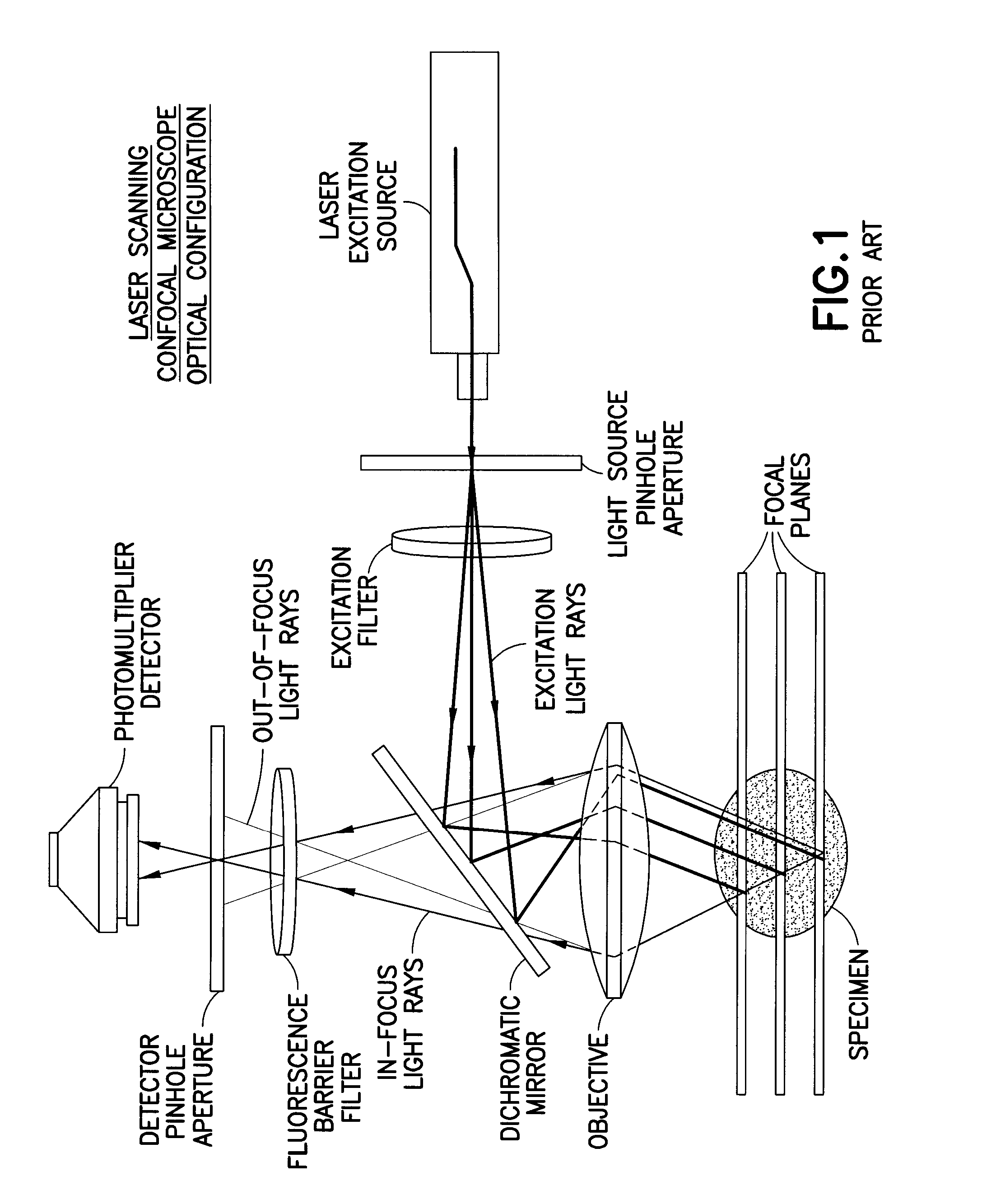
BACKGROUND OF THE INVENTION[0001]1. Field of the Invention[0002]The present invention generally relates to methods for characterizing a sample of porous media using at least one measuring device along with a multipoint statistical (MPS) model. In particular, the invention relates to a method for characterizing flow properties of the sample whereby flow simulation models are generated from one or more set of reflected measured data provided by the at least one measuring tool in combination with the MPS model.[0003]2. Background of the Invention[0004]The principle of confocal imaging was patented by Marvin Minshy in 1957 (see U.S. Pat. No. 3,013,467 dated Nov. 7, 1957 issued to Marvin Minshy). In a conventional fluorescence microscope, the sample is flooded in light from a light source. Due to the aspects of light intensity traveling over a distance, all parts of the sample throughout the optical path will be excited and the fluorescence detected by a photodetector.[0005]However, conf...

Claims


Application Information

Patent Timeline
Patent Type & Authority Applications(United States)
IPC IPC(8): G06F17/50G06T17/00G06F17/18G06G7/48
CPCG06T17/00G02B21/0024
Inventor HURLEY, NEIL FRANCISZHANG, TUANFENGXU, GUANGPINGXU, LILISLIM, MIRNA
Owner SCHLUMBERGER TECH CORP
Why Eureka
Try Eureka