[0011]The present invention provides methods and systems for preparing container inventories of
bicarbonate medical buffer solutions (buffers) having a precisely controlled pH with minimum variability among the solutions in any individual container. By providing such inventories of buffer containers where the buffer in each container has an identical pH (within a very small tolerance, typically±−0.03), the buffers can be used to control the pH of other medical solutions, such as local anesthetics, to a predictable physiologic pH by combining a predetermined volume of the buffer with the medical solution. In this way, the buffered pH of the combined buffer and medical solution will also be precisely controlled and predictable, a result that would not be possible if the pH of the
buffer solution were not itself precisely controlled and predictable.
[0013]In buffering medical solutions, including local anesthetics such as
lidocaine, articaine, prilocalne, and mepivacaine, both the amount of the buffering solution and the pH of the buffering solution can have a significant effect on the “buffered” pH of the combined solutions. Viewed differently, the amount of buffering solution needed to stabilize a medical solution at a particular target pH will depend on the pH of the buffering solution itself. Thus, a measured volume of buffering solution cannot be relied on to adjust the pH of a medical solution toward a target pH when the actual pH of the buffering solution vary significantly from its nominal pH, and the stabilized pH of the buffered medical solution can differ significantly from the target value. Conversely, by providing inventories of medical buffer solutions having precisely controlled and highly predictable pH values in accordance with the present invention, the user can adjust the pH of a
local anesthetic or other medical solution in a highly predictable manner by combining a predetermined or calculated volume of the buffer with a given volume of the medical solution.
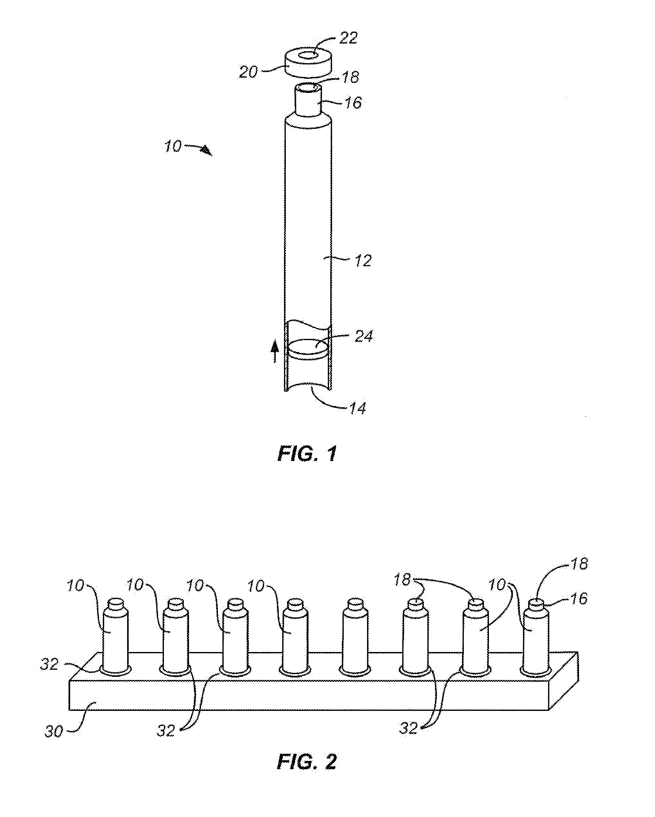
[0014]In a first aspect of the present invention, a method for adjusting pH of a bicarbonate buffer in a plurality of buffer containers comprises positioning each of the containers in a chamber with the containers open to
expose the buffer inside each container to a
carbon dioxide containing
atmosphere in the chamber. The pressure, temperature,
carbon dioxide (CO2) level, and usually
relative humidity within the chamber are controlled to levels selected to provide a target equilibrium pH of the buffer. Maintaining a high
relative humidity level will limit
evaporation from the containers. By “equilibrium,” it is meant that an equilibrium exists between the
partial pressure of the dissolved CO2 in the
buffer solution within the container and the gaseous CO2 in the chamber's
atmosphere. As described above, the pH of the bicarbonate buffer solution depends on the four-way equilibrium between CO2,
carbonic acid,
hydrogen ions, and bicarbonate ions. By providing a virtually unlimited source of CO2 within the chamber at controlled pressure and temperature, the amounts of
carbonic acid and
bicarbonate ion within the buffer solution in each container will be driven to equilibrium values which are precisely equal within ±0.05, preferably within ±0.03, and more preferably within ±0.02. To achieve such precision, the concentration of CO2 and temperature in the
atmosphere within the chamber must be carefully controlled. The atmosphere will preferably be mixed to assure that it is substantially constant in all regions within the chamber. Such mixing can be achieved by introducing and / or recirculating fresh carbon dioxide gas through the chamber and by further mechanically mixing the gas within the chamber, as will be described in more detail below. Optionally, the containers may be vibrated, shaken or otherwise displaced during equilibration to mix the solution within the containers and to prevent pH gradients from forming in the containers.
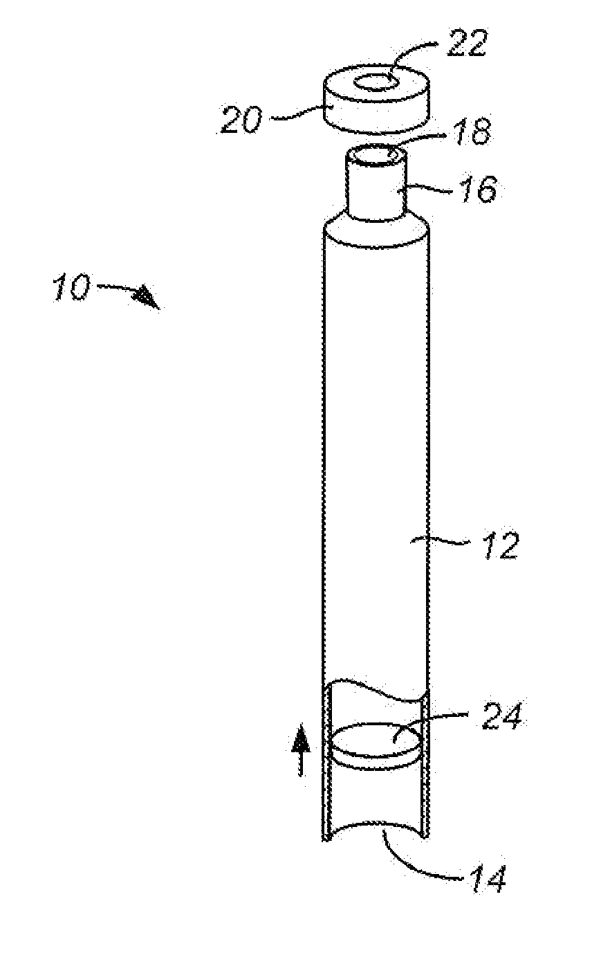
[0019]In a further preferred aspect of the present invention, the containers may have a reduced
diameter neck, where the neck provides the opening through which the gas equilibrates with the buffer solution. In such instances, the reduced area of the neck will limit the surface area of the buffer available for the molecular exchange necessary for equilibration. In such cases, the level of the buffer can be lowered to a larger
diameter region of the container which affords a larger area for the equilibration reactions to occur. The larger area, in turn, will reduce the time needed to achieve equilibrium. After equilibrium has been achieved, the level of the buffer within the container can be raised to eliminate the head space, usually by advancing a plug or other support member within the container to push the buffer solution upwardly to fill the neck. Other means for raising the surface of the solution can also be used, such as reducing the width of the container, introducing an
inert volume (e.g., beads) into the interior of the chamber to displace fluid, or the like.
[0021]The containers may be sealed while they remain within the controlled environment of the chamber. Usually, however, the open containers will be removed from the chamber and sealed outside of the chamber. While it is possible to maintain the controlled environment even outside of the chamber for sealing, it will usually not be necessary.
Exposure of the open containers to a normal atmosphere (without high levels of carbon dioxide) will have little effect on the containers so long as the air-
liquid interface is small in relation to the
fluid volume of the container, and the
exposure is of
short duration, typically less than 10 minutes.
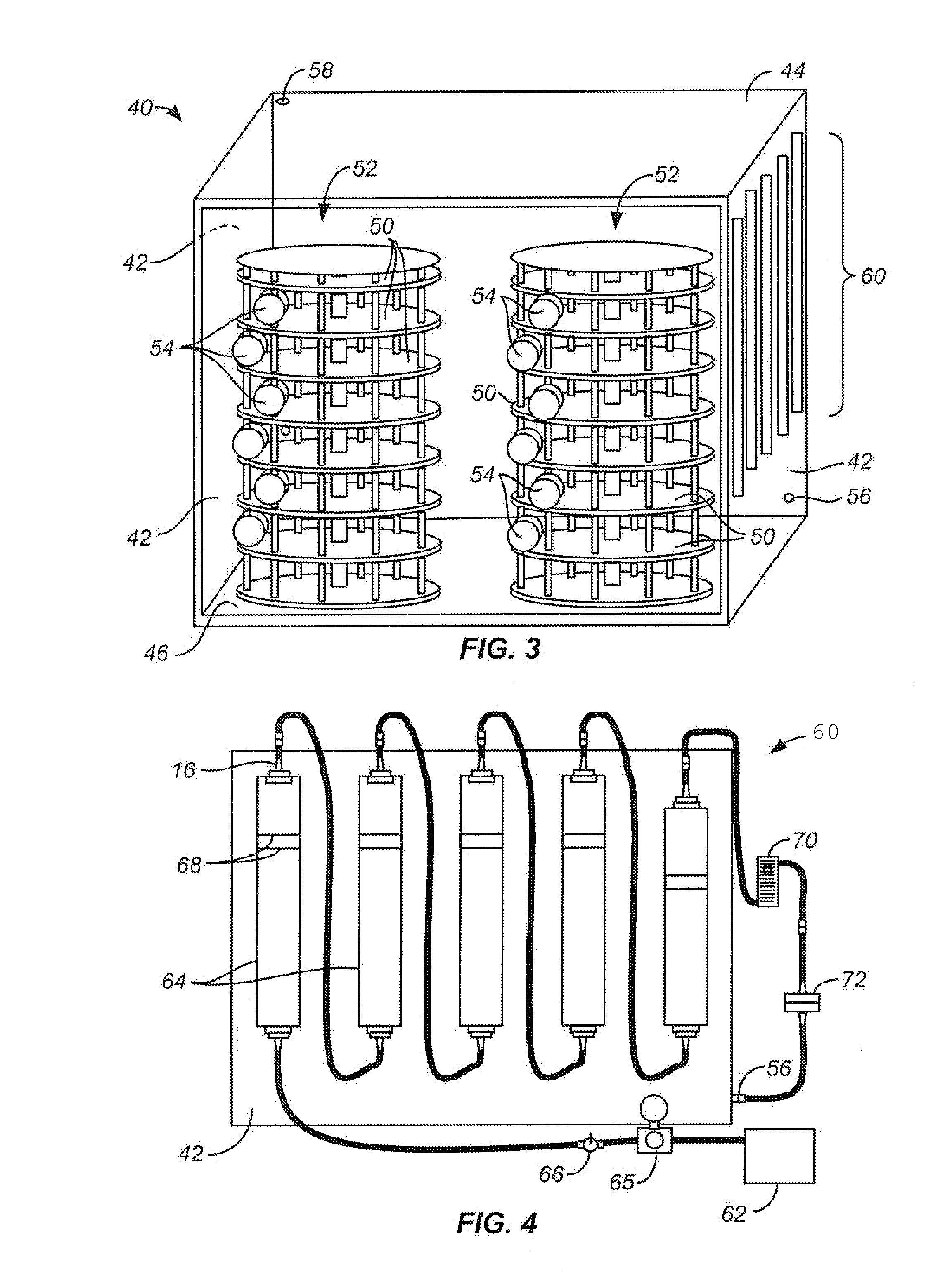
[0023]Usually, the chamber comprises a free-standing cabinet, but the chamber could comprise a room or other structure built within a larger structure. The gas flow will typically flow freely into the bottom of chamber and out the exhaust port at the top of the chamber, where exhaust port is large enough to prevent any buildup of pressure within the chamber. Optionally, the supply lines could be adapted to maintain the temperature of the gas being introduced to the chamber, but typically the temperature within the chamber will be allowed to reach the temperature of the room or other surrounding environment in which the chamber is being maintained. Thus,
temperature control within the chamber will be affected by
temperature control within the room or surrounding containing the chamber. Still another option would be to build one or more of the walls out of a double layer of material, with the space in between being heated or chilled to create the desired temperature. Usually, the
system will further comprise a water bath or
water column, most typically a series of water columns, through which the inlet carbon dioxide gas flow would pass before the gas enters the chamber. Optionally, the last
water column can be maintained at a temperature slightly above the chamber temperature so that the
relative humidity of the gas does not drop when entering the chamber. In the exemplary embodiments, the supports comprise a rotatable carousel having a plurality of stacked, circular shelves, where the shelves rotate adjacent to the multiplicity of pneumostatic passages so that different portions of the shelves will be accessible from each of the pneumostatic passages to facilitate loading and unloading of the supports with the buffer containers. Optionally, the carousel may vibrate, causing the solution in the containers to mix over time, inhibiting the formation of pH gradients that might limit uniform equilibration.


