

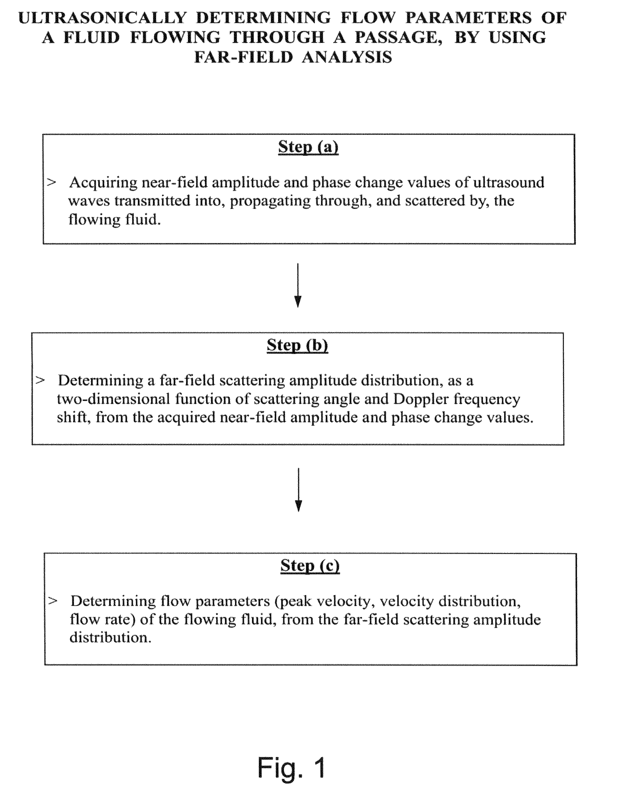
Ultrasonically determining flow parameters of a fluid flowing through a passage, by using far-field analysis
a technology of ultrasonic/sonic/infrasonic diagnostics and flow parameters, which is applied in ultrasonic/sonic/infrasonic diagnostics, instruments, applications, etc., can solve the problems of inapplicability to determining relatively low flow rates and low velocities, and the accuracy of doppler techniques is usually limited
- Summary
- Abstract
- Description
- Claims
- Application Information
AI Technical Summary
Benefits of technology
Problems solved by technology
Method used
Image

Examples
example 1
Ultrasonically Determining Flow Parameters of a Fluid (Liquid Water)Flowing Through a Passage (Silicon Rubber Pipe)
[0212]In Example 1, there was ultrasonically determining flow parameters of a fluid (pure liquid water) flowing through a passage (silicon rubber pipe). The silicon rubber pipe had an inside diameter of 5 millimeters (mm), and a wall thickness of 2 millimeters (mm).
Experimental Procedure
[0213]Example 1 was performed by using the same experimental measuring system which was used, and disclosed, in the present inventors' teachings [20, 21] of their initially developed Near-field / Far-field transformation technique for evaluating and analyzing velocity and vorticity fields in spatial and temporal domains of a laminar or turbulent fluid flowing through a passage. The experimental measuring system was specially adapted and modified for ultrasonically determining flow parameters of a pure liquid water type of fluid flowing through a silicon rubber pipe type of passage, for imp...
example 2
Ultrasonically Determining Flow Parameters of a Fluid (Liquid Water) Flowing Through a Passage (Painted Steel Pipe)
[0228]In Example 2, there was ultrasonically determining flow parameters of a fluid (tap water) flowing through a passage (painted steel pipe). The painted steel pipe had an inside diameter of 102 millimeters (mm), and a wall thickness of 7 millimeters (mm).
Experimental Procedure
[0229]Example 2 was performed by using a similar ‘clamp-on’ type of experimental measuring and data acquisition system as the one used in Example 1, except for changes in the acoustic coupling material and minor changes in the detector array spacing and of the frequency of the transmitted ultrasound waves. The experimental measuring system was specially adapted and modified for ultrasonically determining flow parameters of tap water type of fluid flowing through a painted steel pipe type of passage, for implementing the method of the present invention (as illustratively described hereinabove, wi...
PUM
 Abstract
Description
Claims
Application Information