Implantable medical lead and method for manufacture thereof

a technology of medical leads and medical devices, applied in the field of implantable medical leads, can solve the problems of abrasion or wear of the lead portion that is in contact with the medical device, stressing the distal end, and damage to the tissu

Inactive Publication Date: 2011-01-13
ST JUDE MEDICAL
View PDF21 Cites 38 Cited by
  • Summary
  • Abstract
  • Description
  • Claims
  • Application Information

AI Technical Summary

Benefits of technology

[0012]Thus, an object of the present invention is to provide an improved implantable medical lead which alleviates the problem mentioned above.
[0013]Another object of the present invention is to provide an improved medical lead having a prolonged life time in comparison with prior art medical lead.
[0014]A further object of the present invention is to provide an improved method for selectively designing the properties of a material for use in a medical lead.

Problems solved by technology

The requirements of cardiac leads with respect to material properties or characteristics are contradictory which may be difficult to combine.
Thus, because of the compromise between the different material properties required by the material used in a cardiac lead, this is a complex issue.
As indicated above, a problem is abrasion or wear of the portion of the lead that is in contact with the medical device when implanted.
Since the medical device, which conventionally is implanted in a subcutaneous pocket, is also more or less fixated, such stretching could, in absence of excess lead wire, cause a stressed distal end.
As a result, the portion of the distal end, including e.g. a helix, that is secured to a target tissue, e.g. a heart wall, could cause damages to the tissue.
However, when implanted the medical lead abuts against the surface of the medical device since they are located close to each other and friction between the can of the device and the lead portion abutting the can due to, for example, body movements may cause wear on the lead surface.
However, such a solution only solves part of the complex problem, but more important this solution increases significantly the complexity of joining these components and the difficulty of assembly and manufacturing thereof.
However, this solution does not solve the problem of wear of the surface of the lead.
However, this is a catheter device for an insertion procedure and not intended for implantation.
Also, this prior art does not address the problem related to the wear of the surface of the lead.

Method used


Image

  • Implantable medical lead and method for manufacture thereof
  • Implantable medical lead and method for manufacture thereof
  • Implantable medical lead and method for manufacture thereof

Examples


experiment 1

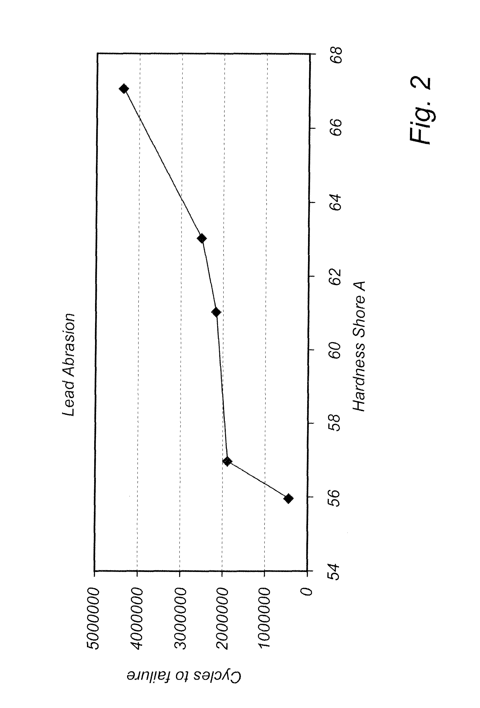
[0042]FIG. 2 presents experimental information showing that the hardness property and abrasion resistance property are related. The test result which relates to a silicone elastomer shows that within a group of otherwise chemically identical, the abrasion resistance increases with increasing hardness. The silicone elastomer or rubbers were cured and post-cured to achieve a specific hardness (Shore A). These were then tested in an abrasion test apparatus, which by St. Jude Medical internally is designated ES-1907 rev X1, designed for measuring the abrasion resistance of pacemaker lead bodies. For this type of abrasion, it has thus been demonstrated that harder materials, of otherwise identical composition as that of the present invention, have greater resistance to abrasion. Thus, it is beneficial to provide softness in the tip for flexibility, but retain hardness in the proximal end to optimize abrasion resistance.

experiment 2

[0043]In FIG. 3, test results for a material according to an embodiment of the present invention, similar to that of the experiment 1, is shown. The graph in FIG. 3 presents abrasion resistance results on a pacemaker lead body made of an Elast-Eon material, more specifically an Elast-Eon 2A material. This material is provided by Aor-Tech. The purpose of such an experiment is to simulate the wear situation of a medical lead in abutment with a medical device can when implanted. The experiment was similarly performed as experiment 1 in the way that the material was first subjected to heat treatment followed by an abrasion test. The abrasion test was performed according to a St. Jude Medical internal test method called 60010764 rev P02. The result shows that the lower hardness material, i.e. less stiff as indicated by lower Young's modulus, from a heat treatment at 120 C / 6 hrs has a lower abrasion resistance compare to material treated at 85 C / 4 h that has higher stiffness / hardness / modu...

experiment 3

[0045]FIG. 4 shows the relationship between stiffness, indicated by Young's Modulus, and treatment temperature of a polymer sheet material according to an embodiment of the invention. The experiment was performed by first heat treating an Elast-Eon 2A material in a conventional oven. In FIG. 4, the name Optim is used which is a name of the Elast-Eon 2A material used at St. Jude Medical. Thereafter, the stiffness was then measured by a conventional apparatus for measuring tensile properties of stress versus strain. Lloyd Instruments LRX plus ExT with 10N load cell tested on tubing in a mandril clamp with 100 mm gauge length. The graph shows that a higher treatment temperature results in a lower stiffness of the polymer material or Elast-Eon 2A provide by Aor-Tech.

Heat Treatment Process

[0046]As is understood by the skilled person in the art, the heat treating process according to the present invention may be performed in number of alternative ways. In an example method for manufacturi...


PUM

PropertyMeasurementUnit
temperatureaaaaaaaaaa

Abstract

An implantable medical lead for implantation in a patient which has at least one electrical conductor connected to at least one electrode and / or sensor of said lead. The at least one conductor is arranged within a continuous sheet of a polymer material. A distal portion of the lead is adapted to be located in or at a heart of said patient and a proximal portion of said lead is connectable to an implantable medical device and arranged such that, when connected to the device, at least a part of the proximal portion of the sheet is placed in close proximity to said medical device. At least the proximal portion of the polymer sheet material is processed in at least a first heat process stage such that an inherent resistance to wear of the polymer sheet material is substantially maintained, and the distal portion of said polymer sheet material is processed in at least a second heat process stage in which a polymer morphology of said polymer material is altered such that an inherent flexibility of the polymer sheet material is substantially increased.

Description

BACKGROUND OF THE INVENTION[0001]1. Field of the Invention[0002]The present invention generally relates to the field of implantable medical devices. More specifically, the present invention relates to an implantable medical lead for implantation in a patient, the lead having a distal end adapted to be located within or at a heart of the patient and a proximal end connectable to an implantable medical device.[0003]2. Description of the Prior Art[0004]Within the field of implantable medical device, such as heart stimulators or pacemakers, implantable leads are used for conveying electrical stimuli from the device to a distal portion of the lead, e.g. to the myocardium of a human heart, for instance the endocardium and to transfer signals, for example, signal representative of electrical activity of the heart to the device. The requirements of cardiac leads with respect to material properties or characteristics are contradictory which may be difficult to combine. For example, a distal ...

Claims


Application Information

Patent Timeline
Patent Type & Authority Applications(United States)
IPC IPC(8): A61N1/00B32B5/14
CPCA61N1/0565A61N1/056B29C71/0063B29C71/02B29C2071/022
Inventor DOWLING, KENNETH
Owner ST JUDE MEDICAL
Why Eureka
Try Eureka