

Fuel vapor processors
- Summary
- Abstract
- Description
- Claims
- Application Information
AI Technical Summary
Benefits of technology
Problems solved by technology
Method used
Image

Examples
second embodiment
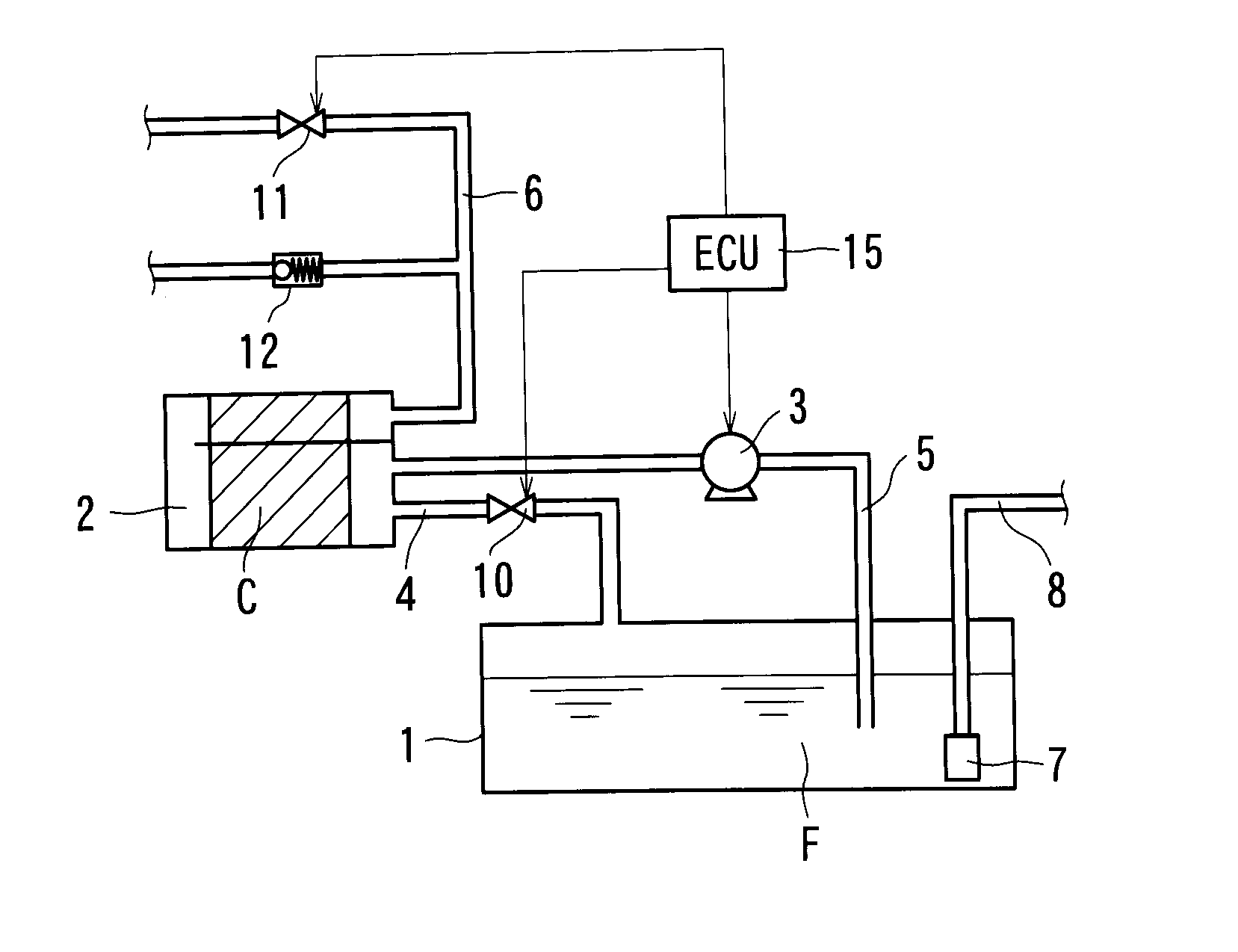
[0058]As shown in FIG. 2, the recovery pipe 5 is communicated with an air intake pipe 17 via a purge pipe 18 between the canister 2 and the vacuum pump 3 in the The purge pipe 18 is provided with a purge pipe valve 19 for switching an open state and a closed state of the purge pipe 18. The purge pipe valve 19 is composed of a solenoid valve controlled by the ECU 15. The air intake pipe 17 is provided with a throttle valve 20 for controlling an amount of air intake, and is connected with an air cleaner 21. In addition, the air pipe 6 between the air pipe valve 11 and the canister 2 is communicated with a pipe equipped with a one-way valve 22, which allows gas flow from the canister 2 toward the outer space. Further, the fuel tank 1 is provided with a pressure sensor 23 for detecting inner pressure of the fuel tank 1. The pressure sensor 23 is one example of the inner pressure detector. The inner pressure detected by the pressure sensor 23 is translated into signals, and then the sig...
first embodiment
[0059]In a state that the ignition switch or the like is off, the vapor pipe valve 10 is open, whereas the air pipe valve 11 and the purge pipe valve 19 are closed. When the fuel vaporizes in the fuel tank 1 in this state, the fuel vapor is led into the canister 2 via the vapor pipe valve 10 like the first embodiment, however air passing through the canister 2 is released into the atmosphere via the one-way valve 22. When the ignition switch or the like is turned on, the air pipe valve 11 and the purge pipe valve 19 are opened. In addition, when the engine is driven, air is led to the engine from the air cleaner 21 while controlling flow rate of air in the air intake pipe 17 due to the throttle valve 20. Then, negative pressure in the air intake pipe 17 acts on the purge pipe 18, so that the fuel vapor is removed from the canister 2 due to the negative pressure and is delivered into the engine through the purge pipe 18 and the air intake pipe 17. In this state, the air pipe valve 11...
fifth embodiment
[0076]In addition, in the fifth embodiment, the second pressure regulation valve 40 can be disposed on the second circulation pipe 52. In this case, pressurized force due to the pressure pump 34 acts on the receiving chamber 50 for the third separation membrane 48 in addition to the receiving chamber 27 for the first separation membrane 25 and the receiving chamber 31 for the second separation membrane 29, so that separation efficiency by the third separation membrane 48 is further increased.
[0077]A sixth embodiment has a pressure swing adsorption device in addition to the basic configuration of the first embodiment. In particular, as shown in FIG. 10, a four-way valve 55 is disposed on the recovery pipe 5, and the pressure swing adsorption device (PSA) 56 is communicated with the four-way valve 55. The PSA 56 is two-tower type PSA having a first adsorption tower 56a and a second adsorption tower 56b parallel to each other such that when one of the adsorption towers adsorbs the fuel...
PUM
| Property | Measurement | Unit |
|---|---|---|
| Pressure | aaaaa | aaaaa |
| Pressure | aaaaa | aaaaa |
Abstract
Description
Claims
Application Information