
System to enable geothermal field interaction with existing HVAC systems, method to enable geothermal field interaction with existing HVAC system

a technology of geothermal field and hvac system, which is applied in the direction of mechanical conveying drilling, sealing/packing, and borehole/well accessories, etc., can solve the problems of loss of thermal conductance from earth to loop, difficulty in environmental containment of drill site with air rotary drilling, and loss of loop's ability to transfer a considerable percentage of energy, etc., to minimize vibration of drilling equipment, increase depth and therefore capacity, effect of minimizing fractures

Inactive Publication Date: 2011-01-20
GEOTHERMAL TECH
View PDF11 Cites 31 Cited by
  • Summary
  • Abstract
  • Description
  • Claims
  • Application Information

AI Technical Summary

Benefits of technology

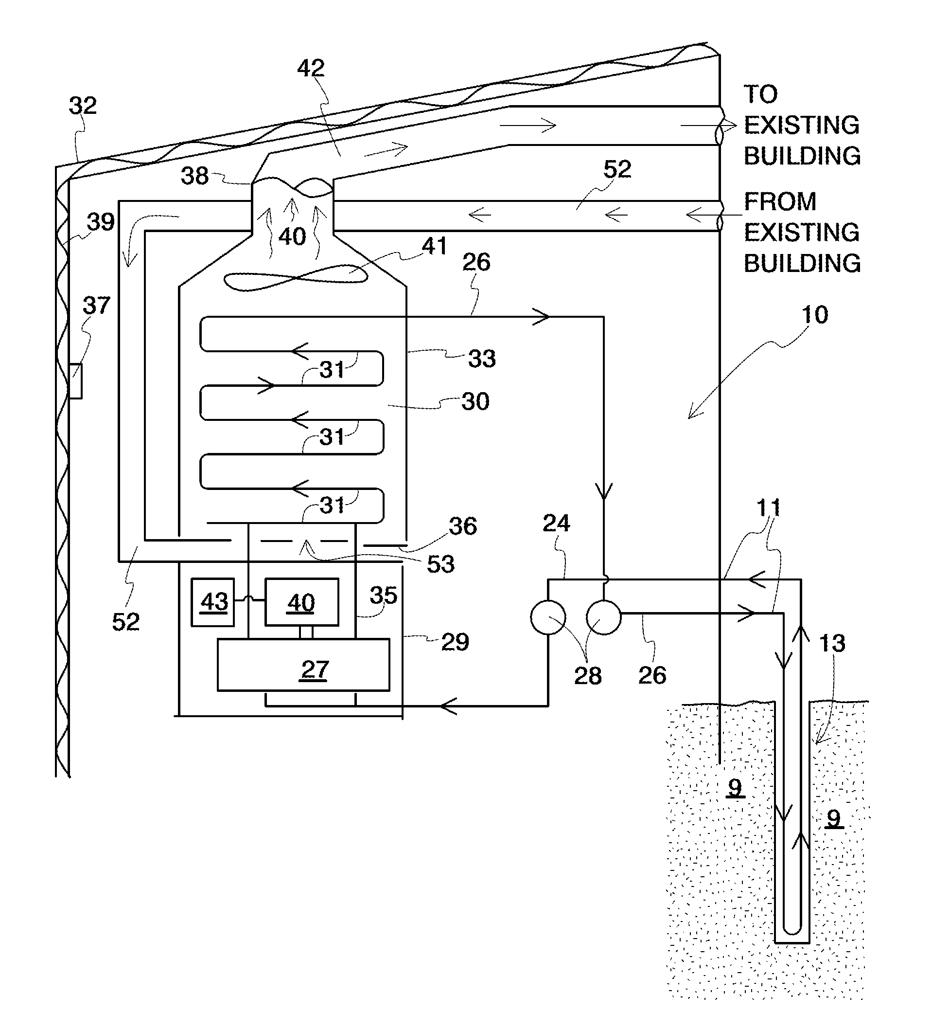
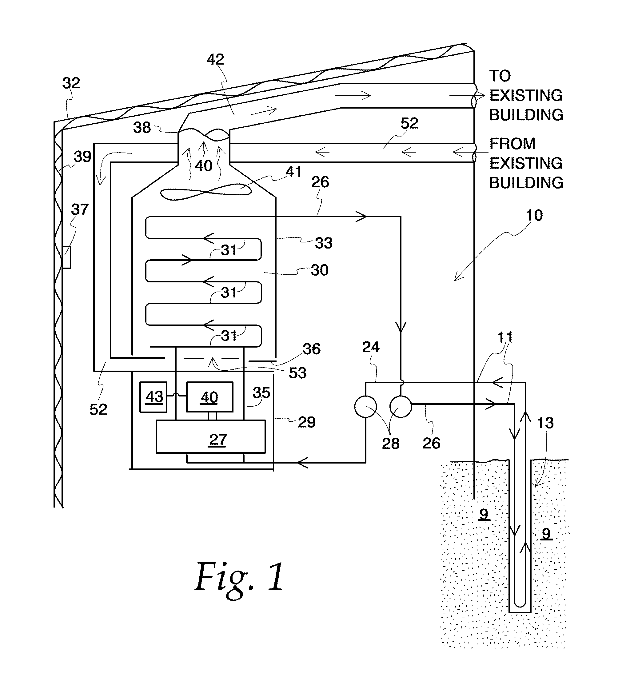
[0027]Another object of the invention is to provide a system for utilizing geothermal energy extracted from a city-lot to supplement energy needs of permanent structures on the city lot. A feature of the invention is a means for utilizing existing HVAC systems of the structures to provide geothermal energy to the structures. An advantage of the invention is no disruption of activity within the structure during the establishment of the geothermal field, or hook up of the field to the HVAC system.

Problems solved by technology

Washout of the well bore caliper, or an unnecessary increase in the diameter of the well bore, results in a loss of the loop's ability to transfer a considerable percentage of energy.
This results in a loss of thermal conductance from the earth to the loop at that point.
Environmental containment of the drill site with air rotary drilling is very challenging.
Fuel consumption of equipment utilizing this method is extremely high due to massive amounts of horse power spent producing huge amounts of air at extremely high pressures.
Other drawbacks to air rotary drilling include disruption of adjacent structures such as aquifers and nearby wells.
Mud rotary drilling is less disruptive to nearby geologic structures, but also less effective in penetrating dense structures even when expensive diamond bits (such as those featuring polycrystalline diamond compact (PDC) inserts) are used.
Also, mud rotary drilling stops working when large cavities develop or are encountered during drilling, inasmuch as mud pressure drops significantly in these scenarios.
A subsequent drop in the return mud volume through the annulus (i.e., the space between the drill string and the sides of the well bore) results in cuttings not being carried to the surface of the hole for evacuation.
This in turn can result in another zone flowing into the wellbore and a catastrophic loss of well control.
But, such systems usually cannot generate enough mud to overcome the aforementioned pressure and / or volume drop when large cavities are encountered in consolidated formations.
Three to four wells spaced 20 feet apartment usually can be accomplished in most rural back yards; however the much larger tonnage requirements of high rise buildings and commercial businesses make the possibility of installing geothermal well fields on sidewalks, alley ways, and parking lots a real challenge.
1. The geothermal well drilling industry has no method for assuring a consistent caliper for wells at any depth.
2. Deep well drilling results in massive amounts of water and drilling spoils (cuttings) generated during air rotary drilling. This raises environmental issues.
3. Lack of a method for competitively using mud rotary drilling in consolidated formations. Loss of mud circulation becomes particularly acute in deep drilling. State of the art mud rotary drilling methods are not effective after lost circulation zones are encountered; therefore casings must be set deep through the zone. This casing installation is neither cost effective nor easy to remove.
4. Deterioration of silica sand-based grout during air rotary drilling in deep consolidated formations. This leads to contamination of fresh water aquifers.

Method used


Image

  • System to enable geothermal field interaction with existing HVAC systems, method to enable geothermal field interaction with existing HVAC system
  • System to enable geothermal field interaction with existing HVAC systems, method to enable geothermal field interaction with existing HVAC system
  • System to enable geothermal field interaction with existing HVAC systems, method to enable geothermal field interaction with existing HVAC system

Examples


example

[0149]FIGS. 3A and 3B are caliper logs depicting a location where fractured formation and lost circulation zones are an issue. The logs depict fracture zones at depths of 195 feet, 250 feet and 375 feet. These two holes were drilled 100 feet from each other, on the same day.

[0150]FIG. 3A is a caliper log for a hole drilled using conventional drilling techniques. From a 180 foot depth, a mud rotary was switched to air rotary due to the driller encountering the fractured formation. Caliper deviations (i.e., washout) seen on that graph are concomitant with lost circulation.

[0151]FIG. 3B is a caliper log for a hole drilled approximately 100 feet away using the invented technique. When the invented reverse auger process was applied at the first instance of mud pressure drop, the fractures sealed, or at least were greatly minimized. The reverse auger method was used in this drilling at between 180 and 260 feet. Upon repair of the fractures, the mud circulation was reestablished. Unlike th...


PUM


Abstract

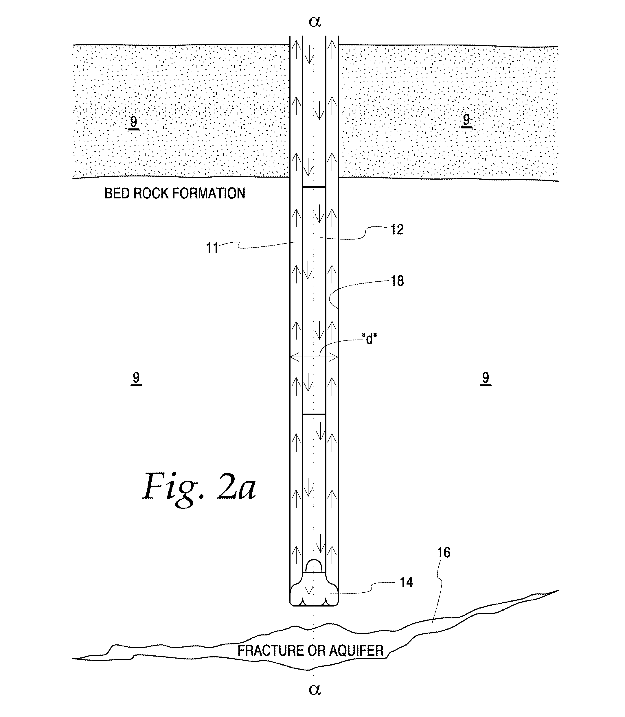
The invention provides a system for adapting an HVAC system in an existing building for utilizing geothermal energy, the system comprising an incoming flux of geothermal energy; a plurality of heat exchange surfaces adapted to receive the incoming flux of geothermal energy; and an interface between the HVAC system and the heat exchange surfaces, said interface adapted to transfer the geothermal energy to the system. Also provided is a method for repairing aberrations in drill borings, the method comprising using a rotary mud drill system to produce a drill hole up to the location of the aberrations; removing the rotary mud drill from the drill hole; inserting an auger into the drill hole to a point directly above the location of the aberrations; actuating the auger; introducing loose substrate into the drill hole; allowing the substrate to contact the auger; and lifting and lowering the auger along longitudinally extending regions of the drill hole defining the aberrations for a time and in substrate amounts sufficient to fill the aberrations. The invention also provides a system which facilitates rotating drill bits at an rpm which are multiples faster than their associated drill strings.

Description

PRIORITY[0001]This application claims the benefits of U.S. Provisional Application Nos. ______, filed on ______.BACKGROUND OF THE INVENTION[0002]1. Field of the Invention[0003]This invention relates to a system and a method to enable widespread adoption of geothermal energy and more particularly this invention relates to a system and a method for facilitating energy transfer from a geothermal field to an existing HVAC system of a building with minimal retrofit, thereby enhancing or retro fitting existing conventional HVAC systems with minimal interference of daily activity within the building.[0004]2. Background of the Invention[0005]Geothermal energy is an alternative energy source existing under ground. The goal for geothermal energy use is to utilize the typical midrange constant temperatures of 52 to 54° F. found beneath the earth's surface to help heat or cool a structure in winter or summer, respectively.[0006]Conventional geothermal well fields are drilled with wells having u...

Claims


Application Information

Patent Timeline
Patent Type & Authority Applications(United States)
IPC IPC(8): F24J3/08E21B33/13E21B33/138E21B4/20
CPCE21B7/005E21B33/138Y02E10/14F24J2003/088F24J3/085F24T10/20F24T2010/53Y02E10/10
Inventor SHELTON, JR., TOMMIE
Owner GEOTHERMAL TECH
Learn More