[0007]Thus, there is a need for a
diagnostic system which detects defects of devices under test, identifies their physical causes and localizes the positions of the defects. This measurement should be performed with high accuracy within a short time while the device under test is operated in a normal (production) environment and ambient noise emitted by unknown sources may affect the measured signal p(t,ri). A further object is to use a minimum of hardware elements to keep the cost of the
system low.SUMMARY OF THE INVENTION
[0008]According to the present invention, the present
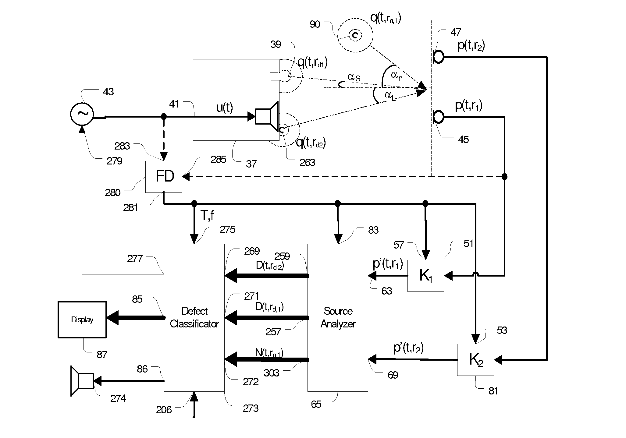
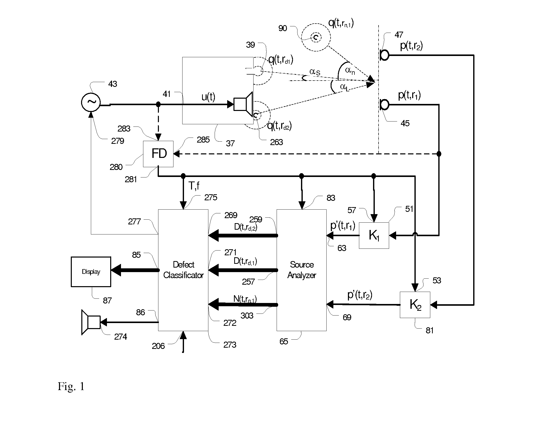
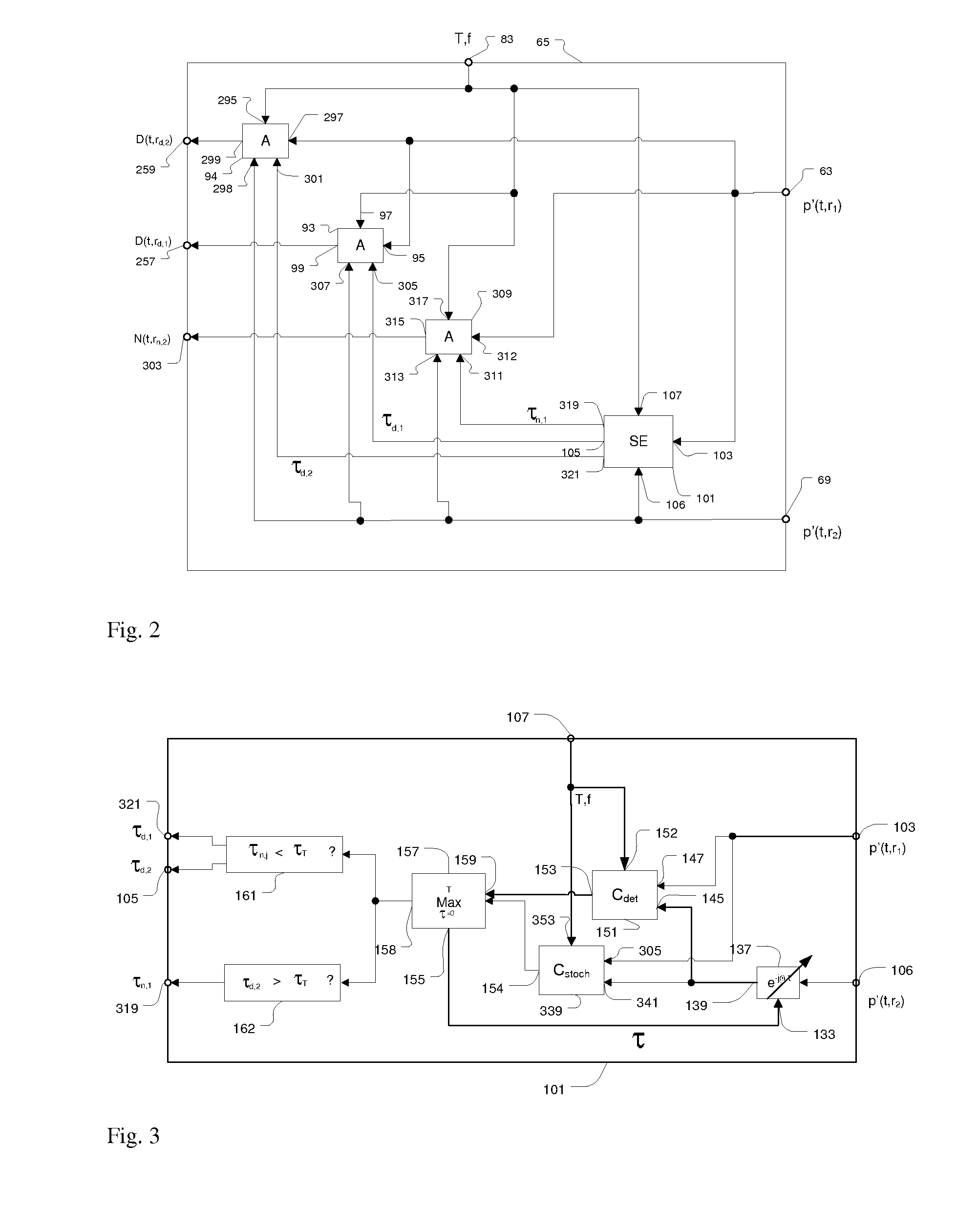
diagnostic system monitors signals p(t,ri) at multiple measurement points ri (with 1≦i≦I) which are affected by defect sources q(t, rd,j) (with 1≦j≦J) of the device under test at position rd,j and by ambient noise sources q(t, rn,k) at position rn,k (with 1≦k≦K). In contrast to prior art, a source analyzer separates the signals emitted by the defect sources q(t, rd,j) and noise sources q(t, rn,k) by combining
spatial analysis and signal analysis to
exploit information about the location of the sources and properties of stochastic and deterministic
distortion components emitted by the sources. The linear part plin(t,ri), which is coherent with the stimulus u(t) may be suppressed by filtering because this part contains no significant clues about some defects of the device under test. The
spatial analysis performed by the source analyzer includes the identification of the number of sources, the classification into defect and noise sources and localization of the sources. The source analyzer generates defect vectors D((t,rd,j) and noise vector N(t,rn,k) which comprise deterministic components pdet(t,rd,j) and pdet(t,rn,k), stochastic components n r and pstoch(t, rn,k) and information about the position of each identified source τd,j and τn,k corresponding with the separated defect and noise sources, respectively. The signal analysis applied to the separated source signals increases the sensitivity of the
diagnostic system to defects of a device under test which have less energy and similar
spectral properties as ambient noise. The separation of the deterministic components pdet(t,rd,j) and stochastic signal components pstoch(t,rd,j) allows the system to perform an averaging of properties of incoherent signals. Thus, a novel
demodulation technique provides the envelope of modulated stochastic signals as generated by air leaks, and the direction of the source. The signal-to-noise ratio can be improved by increasing the measurement time and averaging the envelope signal over an increased number of periods. Using a periodic stimulus with a time varying
period length T(t)≠T0, such as a sinusoidal sweep, the deterministic components are determined by transforming the measured signal to a constant
period length T0 and averaging the transformed signals in the
phase space.
[0009]The orthogonal features in the defect vector D((t,rd,j) and noise vector N(t,rn,k) are transferred to a defect classificator which determines the quality of the device under test and identifies the physical causes of the defects. The system stays operative if the positions of the sensors, defect and noise sources change. Contrary to known
beam steering techniques, the system requires a low number of sensors and can remain operative with only two sensors. The angle of the
incident wave can be detected with sufficient accuracy because the deterministic and stochastic signal components emitted by the defects comprise many spectral components which cover a wide
frequency band and which are incoherent with the stimulus. However, an array comprising only two sensors has a low
directivity characteristic and cannot separate the defect and noise sources completely, and the measured defect vector D((t,rd,j) may be corrupted by the noise source. In this case, the classificator detects invalid parts of the defect vector D((t,rd,j) automatically by comparing stochastic and deterministic components of the defect vector D((t,rd,j) and of the noise vector N(t,rn,k) with each other and / or with predefined thresholds. According to the invention, the valid parts of the defect vector D((t,rd,j) are stored in an accumulator and are merged with valid parts from repeated measurements using the same stimulus, eventually giving a complete valid
data set. Since most of the ambient noise is a random signal, the accumulation of valid data gives full
noise immunity while keeping the measurement time much shorter than traditional techniques using extensive averaging. The diagnostic system transforms the analyzed data in the defect vector D((t,rd,j) into a lower frequency range where the symptoms of the defects can be analyzed more easily by a
human ear. This auralization technique improves subjective assessment of the defect by a human expert and gives clues for finding the physical cause of the defect. The results of the subjective classification may be provided together with the
objective data in the defect vector D((t,rd,j) to an
expert system which creates a
knowledge base for the automatic classification of the defects.

