Patient Management Support System for Patient Testing and Monitoring Devices

a technology for monitoring devices and patient management, applied in the direction of mechanical pattern conversion, computer security arrangements, instruments, etc., can solve the problems of not fully embracing the communications business' medical business requirements, requiring significant human labor for interaction and coordination by multiple parties, and limiting the use of wireless devices to cardiac/patient patients

Inactive Publication Date: 2011-01-20
BARTON KENNETH EDWARD
View PDF4 Cites 32 Cited by
  • Summary
  • Abstract
  • Description
  • Claims
  • Application Information

AI Technical Summary

Problems solved by technology

The wireless devices are mostly limited to cardiac / patient status monitors worn by the patient, wireless to a unit in the hospital room and connected via wire line to remote monitoring within the confines of the facility.
This requires significant human labor for interaction and coordination by multiple parties to monitor and react to patient condition changes as recorded by current testing and monitoring devices.
One of the difficulties in providing a communication solution (i.e., hard-wired or wireless based service) for PTMSS devices has been that at the same time electronic medical technology has evolved, so has the technology in the communications arena.
However, during these evolving processes of technologies, the requirements of the medical business were not fully embraced by the communications business.
The communications business has only supported certain limited applications of the healthcare business rather than seeking to understand the overall requirements of health care.
These devices are limited in that they are medical testing and monitoring devices, adapted to work on a specific communications network.
Such Systems provide limited functionality and do not provide a fully integrated solution.
Currently there is no common data structure protocol or technology that provides the functionality and security that the PTMSS can provide.
Furthermore, the information is not regularly integrated by indices, collated or monitored for specific parameters and provide limited functionality in applications such as automatic notification (e.g., clinical alerts).
Conversely, the medical business does not fully understand the communications business and has predominantly sought communications support for specific applications and not overall patient care and management solutions.
Solutions that do include long-range wireless communications provide limited functionality.
Additionally, the networks have to be integrated into existing systems and do not work well within the confines of the physical clinical or hospital environment.
The very construction of hospitals and clinics with significant piping, electrical and air handling systems tend to interfere with wireless communications, particularly wireless communications systems that operate at very low power.
This has been an impediment to developing solutions using mobile / cellular networks in the past (most systems have been developed for Point of Care applications).
The structure of the communications business can be complicated for those not directly involved.
Therefore, any system proposed usually fails or has limited effect due to a lack of understanding of the requirements of either party in their respective businesses.
The problem is that Carriers are focused more on providing mobile phone, text messaging, Internet access and content delivery to the consumer market as these are the major profit centers.
Furthermore, the very structure of the Wireless Carrier business limits access by virtue of the way the business is organized.
This structure makes support for devices extremely expensive at the entry level and for the most part, not economically viable.
Current methods in use in patient care are mostly paper based charts and information that have to be entered manually into a patient medical record—then if there is a process in place it might be transcribed into an Electronic Medical Record, therefore introducing the possibility of human error.
There is no single standard or protocol for maintaining patient records, test and / or monitoring data records, clinical alert systems, disease management, validation of information, validation of care, continuity of care or patient tracking.
Although there are many types of software and technology for patient electronic medical record keeping and practice management, they are mostly proprietary stand alone systems, software or technology that often are difficult to integrate into existing database or clinical management systems, if at all, with limited functionality.
However, these devices and the support mechanisms lack any true bi-directional Clinical Alert System support that can be set with patient testing and monitoring parameters, geographic location parameters and provide multiple paths of notification to / from a Physician, Point of Care Facility, the Patient Emergency Medical Services or other entities that may require such notification or interactive communication.
Such systems may have limited or no integration into the various depositories for patient electronic medical records or into associated billing systems.
Systems differ in the size of the stored speech units; a system that stores phones or diphones provides the largest output range, but may lack clarity.
Detecting microtremor during sustained speech was not deemed possible because the EMG activity changed too rapidly.
The experiment was therefore limited to measuring the presence of microtremor in the frequency range of 1 through 20 Hz in sustained vowel phonation, but yielded no positive results.
Many DSP applications have constraints on latency; that is, for the system to work, the DSP operation must be completed within some time constraint.
But these microprocessors are not suitable for application of mobile telephone and pocket PDA systems etc. because of power supply and space limit.

Method used


Image

  • Patient Management Support System for Patient Testing and Monitoring Devices
  • Patient Management Support System for Patient Testing and Monitoring Devices
  • Patient Management Support System for Patient Testing and Monitoring Devices

Examples


Embodiment Construction

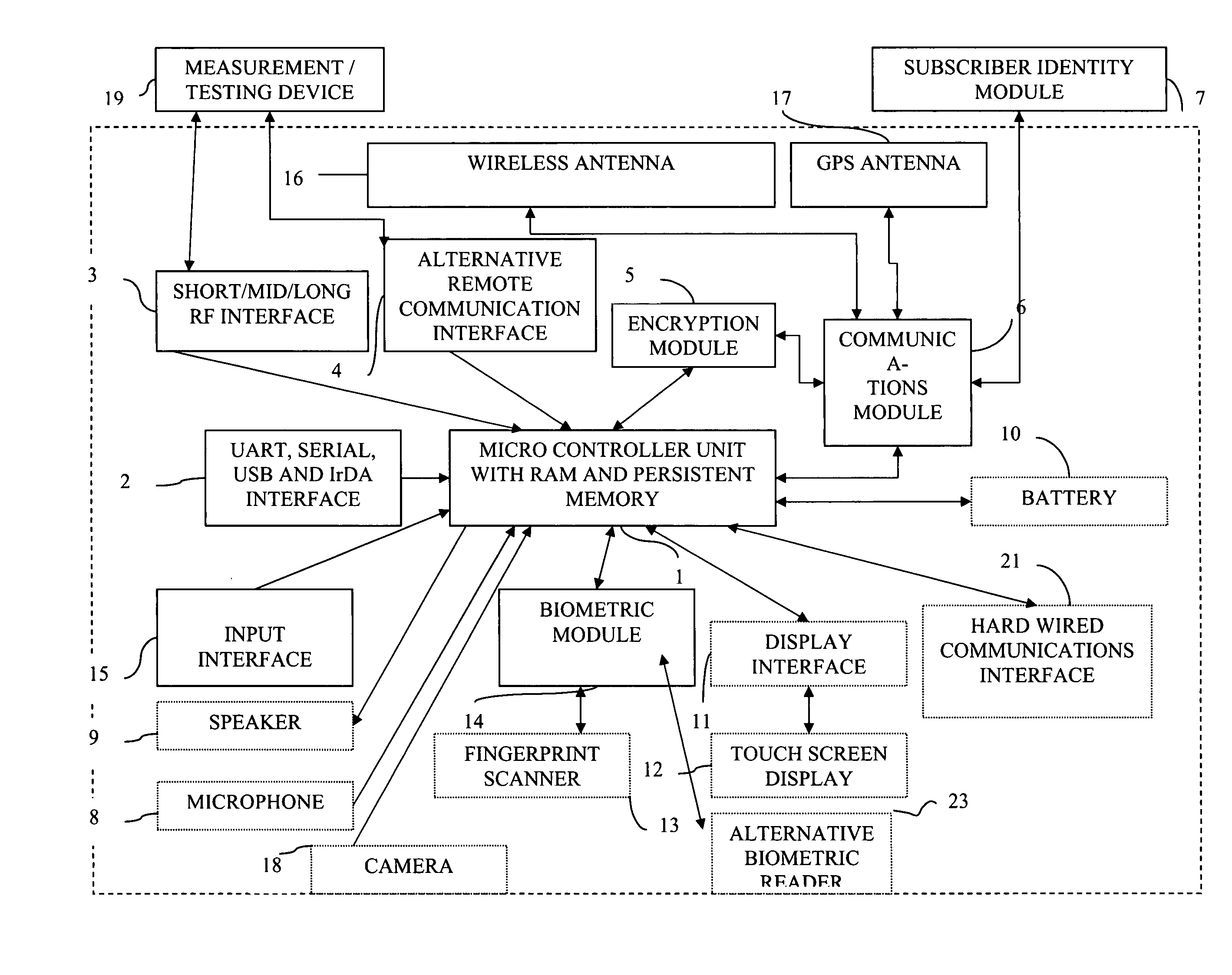
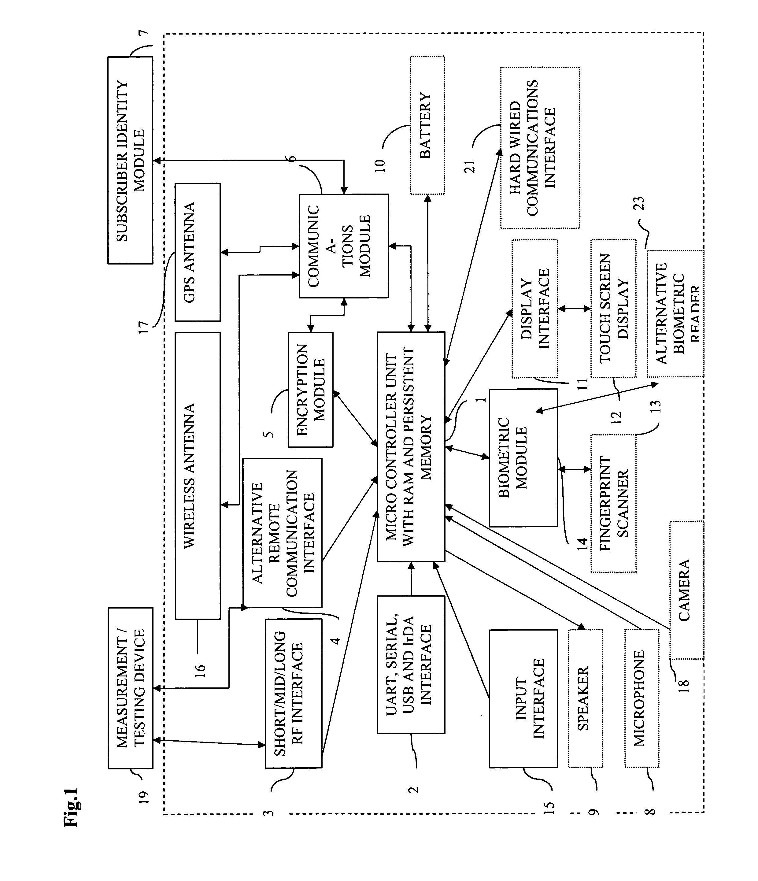
[0243]Referring to FIG. 1, MCU(1) is a heart of Communicator device(24) as it provides controlling function for all modules, listed above. MCU(1) establishes communication channel with (19) by wired means (2) or wireless means (3) or (4). Encryption module (5) may or may not be used in data transmission between (24) and (19) depending on capabilities of (19). Communicator device (24) requests measurement data (100) from (19) via created communication channel and (19) transmits data to (24). Then MCU (1) optionally displays request for biometrical data identification of the user (40) via (11) and (12) or (9). User provides biometric input for analysis via fingertip scanner (13) or alternative biometric reader(23) (Ex. iris scanner) for further processing by (14). Biometric data (90) is processed by (14) and MCU (1) verifies it against stored user biometric data in MCU internal memory (91). If verification is successful, 100 and 101 will be personalized by global unique user id that S...


PUM


Abstract

An information management, analysis and response generation system is used with monitoring devices for the remote testing and monitoring of system users' physiological information (e.g. diabetes testing, blood pressure testing, anti-coagulation, etc.). The information management, analysis and response generation system allows testing and monitoring devices manufactured by third party companies to communicate with the system through existing communication networks means enabled by proprietary technology. Upon analysis of the collected data, the system is capable of initiating communications with third parties, including interactive clinical alert notifications.

Description

FIELD OF THE INVENTION[0001]Embodiments of the invention relate to methodologies, systems and associated methodologies for supporting devices (hard-wired devices and wireless devices) used for measuring and / or testing (e.g., by medical personnel) and monitoring including for testing, self-testing and self-monitoring (e.g., medical patients). These methodologies, systems and associated methodologies for supporting these devices include the integration into electronic systems and records (e.g., patient electronic medical records); evaluating pre-set testing parameters that trigger interactive notifications (e.g., clinical and emergency notifications, primary care physician / medical professional notifications, and patient notifications). These methodologies, systems and associated methodologies for supporting these devices also include integration into other systems (e.g., insurance billing systems, communications and network support billing systems, medical billing systems, patient man...

Claims


Application Information

Patent Timeline
Patent Type & Authority Applications(United States)
IPC IPC(8): G06F3/01G06F15/16G06F17/20H04L9/32G06F21/00G06F40/00
CPCG06F19/3418G06F21/32G06F2221/2101H04L67/12G06F2221/2141H04L63/0861G06F2221/2111G16H40/67
Inventor BARTON, KENNETH EDWARD
Owner BARTON KENNETH EDWARD
Why Eureka
Try Eureka