Piezoelectric vibrating reed, piezoelectric vibrator, oscillator, electronic device, radio-controlled clock, and method for manufacturing piezoelectric vibrating reed

a piezoelectric and vibrating arm technology, applied in the field of piezoelectric vibrating arm, can solve the problems of vibration loss (leakage of vibration energy) through the base portion, the vibration performance of the vibrating arm will decrease, and the vibration loss of the vibrating arm is likely to occur easily. , to achieve the effect of improving reliability, high quality and low disconnection possibility

Active Publication Date: 2011-01-27
SII CRYSTAL TECH
View PDF4 Cites 5 Cited by
  • Summary
  • Abstract
  • Description
  • Claims
  • Application Information

AI Technical Summary

Benefits of technology

[0051]In the oscillator, electronic device, and radio-controlled clock according to the above aspect of the present invention, since they have the piezoelectric vibrator described above, it is possible to achieve improvement in reliability and high quality.
[0052]According to the piezoelectric vibrating reed and the manufacturing method of the piezoelectric vibrating reed according to the above aspect of the present invention, it is possible to provide a piezoelectric vibrating reed which has a low disconnection possibility and ensures reliability for stable operation without requiring strict exposure position accuracy.
[0053]According to the piezoelectric vibrator, oscillator, electronic device, and radio-controlled clock according to the above aspect of the present invention, since they have the piezoelectric vibrating reed described above, it is possible to achieve improvement in reliability and high quality

Problems solved by technology

However, when the total length of the piezoelectric vibrating reed is reduced by decreasing the length of the base portion, mounting performance thereof will decrease, and the vibrating arm is likely to vibrate unstably.
Thus, vibration loss (leakage of vibration energy) through the base portion can occur easily.
Particularly, since there is an influence of vibration loss, the method of decreasing the length of the base portion is not considered a practically effective method.
However, when the length of the vibrating arm is decreased, the R1 value (series resonance resistance value) increases and the vibration characteristics tend to deteriorate.
Particularly, since the R1 value is proportional to the effective resistance value Re, if the R1 value increases, it is difficult to operate the piezoelectric vibrating reed at low power.
For this reason, the electrode pattern is likely to have a fine pitch, and thus, there is a high risk of midway disconnection during the patterning.
However, in practical cases, the exposure position accuracy will have errors due to mask positioning accuracy or lens aberrations during exposure.
Since the fork portion 207 is a portion where an uneven surface can occur easily, it is generally difficult to form electrodes on the fork portion.
For this reason, it is difficult to achieve high manufacturing efficiency.

Method used


Image

  • Piezoelectric vibrating reed, piezoelectric vibrator, oscillator, electronic device, radio-controlled clock, and method for manufacturing piezoelectric vibrating reed
  • Piezoelectric vibrating reed, piezoelectric vibrator, oscillator, electronic device, radio-controlled clock, and method for manufacturing piezoelectric vibrating reed
  • Piezoelectric vibrating reed, piezoelectric vibrator, oscillator, electronic device, radio-controlled clock, and method for manufacturing piezoelectric vibrating reed

Examples


Embodiment Construction

Piezoelectric Vibrating Reed

[0079]Hereinafter, a piezoelectric vibrating reed according to an embodiment of the present invention will be described with reference to FIGS. 1 to 15.

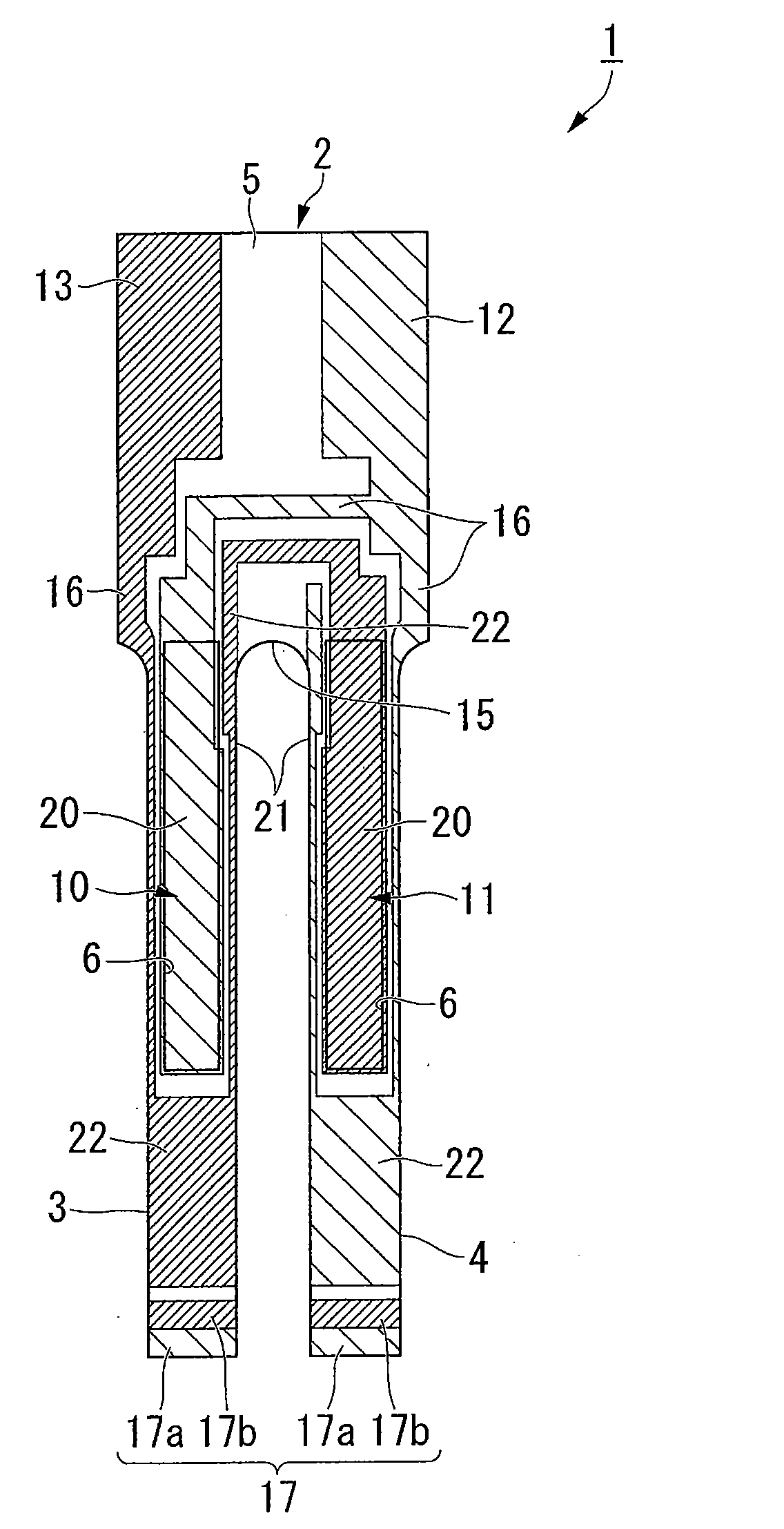
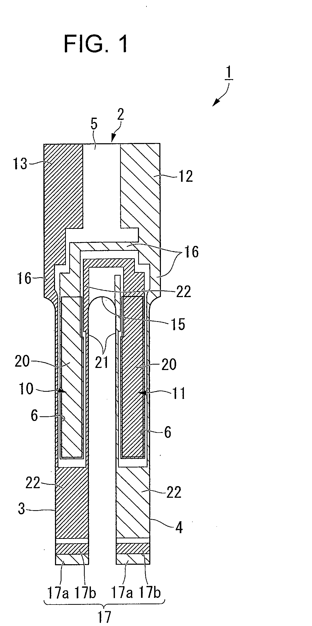
[0080]A piezoelectric vibrating reed 1 according to the present embodiment is incorporated, for example, into a glass-packaged or cylinder-packaged piezoelectric vibrator of the surface-mounting type. As shown in FIGS. 1 and 2, the piezoelectric vibrating reed 1 includes a turning-fork type piezoelectric plate 2 made of a piezoelectric material such as quartz, lithium tantalate, or lithium niobate.

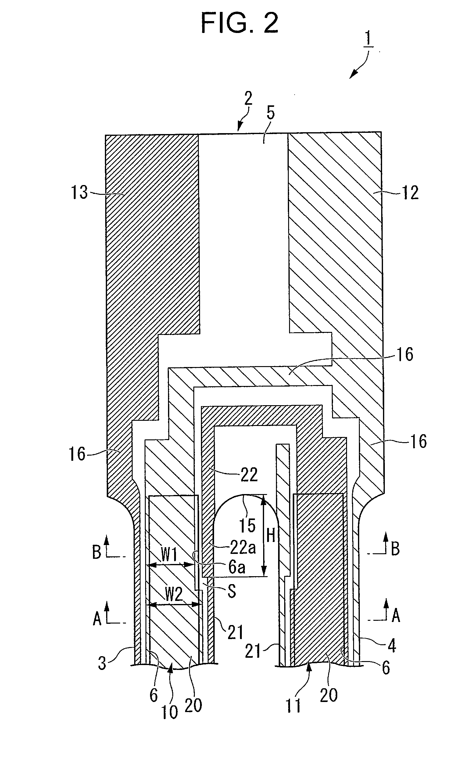
[0081]FIG. 1 is a top view of the piezoelectric vibrating reed 1. FIG. 2 is an enlarged view of base ends of vibrating arms 3 and 4 shown in FIG. 1.

[0082]The piezoelectric plate 2 includes a pair of vibrating arms 3 and 4 disposed in parallel to each other and a base portion 5 to which the base ends of the pair of vibrating arms 3 and 4 are integrally fixed. Moreover, on the principal surfaces (top and back surfa...


PUM

PropertyMeasurementUnit
widthaaaaaaaaaa
widthaaaaaaaaaa
widthaaaaaaaaaa

Abstract

Providing a piezoelectric vibrating reed which has low disconnection possibility and ensures reliability for stable operation without requiring strict exposure position accuracy. A piezoelectric vibrating reed 1 including: a piezoelectric plate which includes vibrating arms 3 and 4, a base portion 5 to which base ends of vibrating arms are integrally fixed, and groove portions 6 which are formed on principal surfaces of vibrating arms; and excitation electrodes 10 and 11 to which vibrating arms are vibrate, wherein the excitation electrodes each include: a principal electrode portion 20, a side electrode portion 21 and a connection electrode portion 22, wherein the principal electrode portions are formed such that a horizontal width W1 on the base end sides of the vibrating arms is smaller than a horizontal width W2 in other portions so that a vacant area S is secured on a portion of the principal surface of each of the vibrating arms in the vicinity of a fork portion 15, and wherein the connection electrode portion is formed to have a large width on the principal surface of each of the vibrating arms so as to come close to an opening end side of each of the groove portions by occupying the vacant area.

Description

RELATED APPLICATIONS[0001]This application claims priority under 35 U.S.C. §119 to Japanese Patent Application No. 2009-170381 filed on Jul. 21, 2009, the entire content of which is hereby incorporated by reference.BACKGROUND OF THE INVENTION[0002]1. Field of the Invention[0003]The present invention relates to a piezoelectric vibrating reed made of a piezoelectric material, such as quartz or lithium tantalate, a piezoelectric vibrator having the piezoelectric vibrating reed, and an oscillator, an electronic device, and a radio-controlled clock each having the piezoelectric vibrator, as well as a manufacturing method of the piezoelectric vibrating reed.[0004]2. Description of the Related Art[0005]Recently, a piezoelectric vibrator utilizing quartz or the like is used in a cellular phone and a portable information terminal as the time source, the timing source of a control signal, a reference signal source, and the like. The piezoelectric vibrator of this type is proposed in a variety...

Claims


Application Information

Patent Timeline
Patent Type & Authority Applications(United States)
IPC IPC(8): H01L41/047H01L41/04H01L41/22H01L41/09H01L41/18H01L41/23H01L41/29H01L41/313H01L41/332H01L41/338H03B5/32H03H3/02H03H9/02H03H9/19H03H9/215
CPCH03H3/04H03H9/1021Y10T29/42H03H2003/0492G04R20/10H03H9/215
Inventor KOBAYASHI, TAKASHI
Owner SII CRYSTAL TECH
Why Eureka
Try Eureka