Dc-dc converters

a converter and dc technology, applied in the field of voltage converters, can solve the problems of under- or overvoltage, short switch on i.e. conduction, times, and increased switching speed

Active Publication Date: 2011-01-27
CIRRUS LOGIC INC
View PDF16 Cites 74 Cited by
  • Summary
  • Abstract
  • Description
  • Claims
  • Application Information

AI Technical Summary

Benefits of technology

[0021]It is therefore an aim of the present invention to provide methods and apparatus for control of DC-DC converters which at least mitigate at least some of the above mentioned problems.

Problems solved by technology

These trends result in two design challenges for DC-DC converters to service these applications: one induced by the choice of the value of the low voltage; the other by battery technology lagging behind the change to lower processor supply voltages.
If the control over the processor supply voltage is not sufficient, problems with under- or overvoltage may occur; both are equally undesirable.
This, coupled with the desire for small external components pushes the DC-DC converter to high operating frequencies, resulting in extremely short switch on i.e. conduction, times. The increase in switching speed afforded by the reduction in transistor feature size is not normally available for the power switches since the interface components must be rated to battery voltage.
Since small conduction periods, i.e. on times, of the power switches are difficult to control, it is becoming increasingly difficult to control the lower processor output voltages with adequate accuracy using traditional Peak Current Mode control methods.
One known problem with DC-DC converters is voltage overshoot and large in-rush currents on start-up of the converter.
This is especially an issue for Valley Current Mode converters as the high side device driver current is only indirectly controlled.
Another known problem with DC-DC converters is providing current limit protection for current overload situations such as protection against short-to-ground.
However, in a short-to-ground situation the voltage difference across the inductor can be high during the PMOS conduction period and near zero during the NMOS conduction period, with the result that the inductor current decays slowly.

Method used


Image

  • Dc-dc converters
  • Dc-dc converters
  • Dc-dc converters

Examples


Embodiment Construction

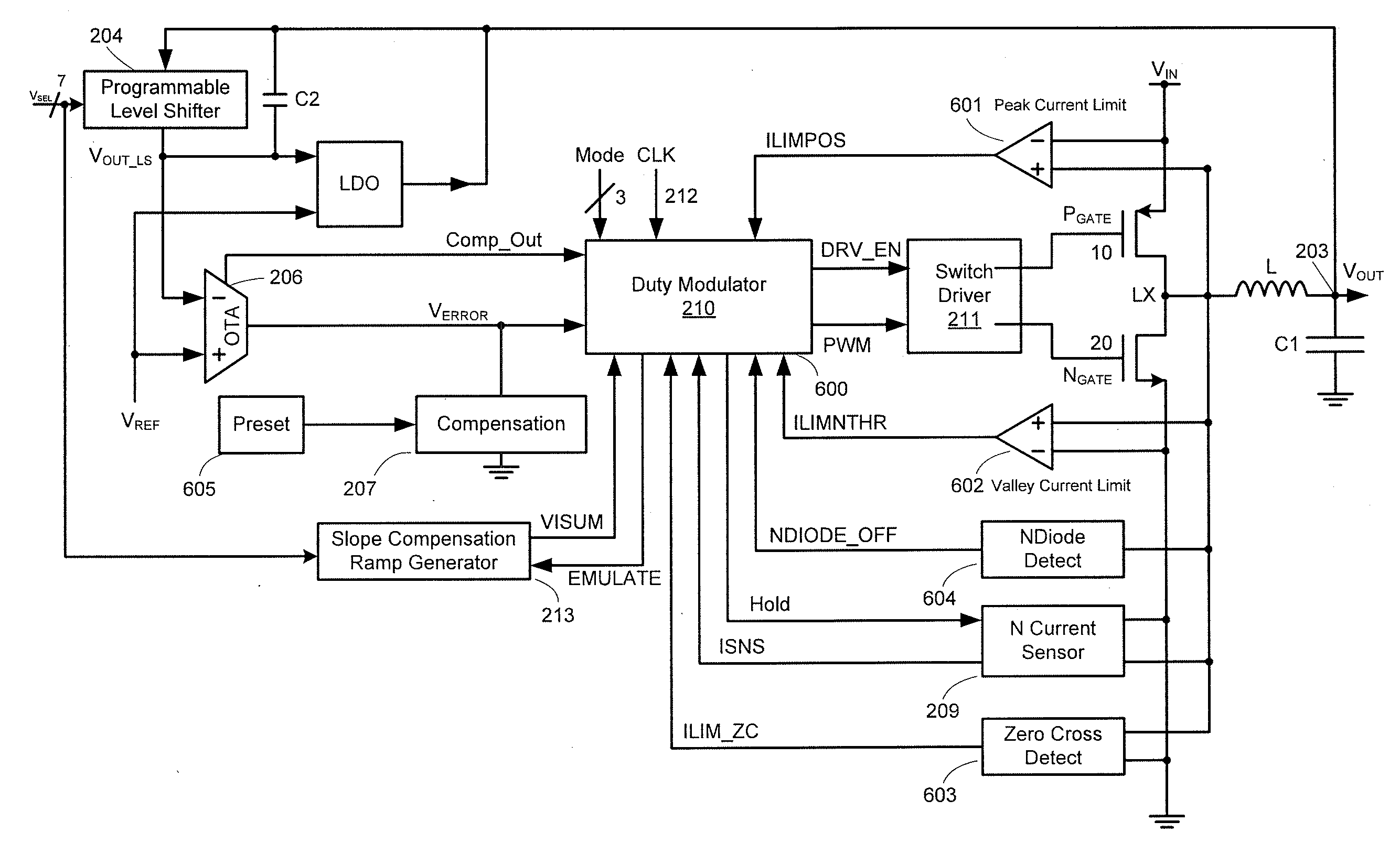
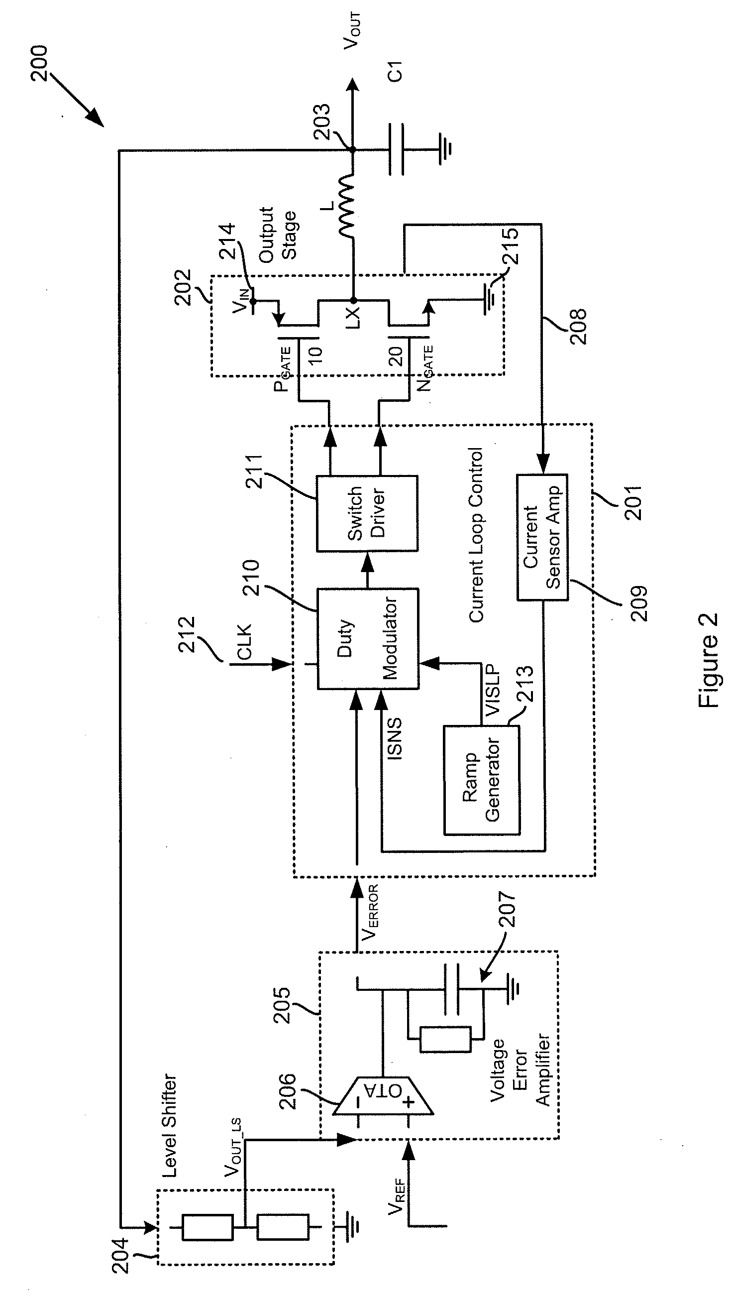
[0083]As discussed above FIG. 2 shows a conventional DC-DC converter. As described above, in operation, a signal representative of the current in the inductor is compared with the VERROR signal to control switches 10 and 20.

[0084]The inductor current could be sensed using a series resistor in series with the inductor or the respective transistor. However the use of such series resistors introduces an extra source of resistive power loss and thus reduces the efficiency of the converter. Efficiency is, especially for battery powered devices, an important consideration. It is preferable therefore to use “lossless” sensing techniques; for example to sense the drain-source voltage across the PMOS due to its on resistance. This gives a voltage proportional to the PMOS current.

[0085]In operation of a conventional peak mode DC-DC converter the PMOS switch is turned on at an edge of the clock signal 212. In the lossless current sensing approach, i.e. in embodiments not having a sense resisto...


PUM


Abstract

Apparatus and method for providing current limiting in a DC-DC converter and especially to methods and apparatus suitable for a start-up mode of operation. The invention monitors the inductor (L) current when the high side supply switch is on against a peak current limit threshold. If the inductor current reaches the peak current limit threshold the high side switch is turned off. The inductor current when the low side switch is off is monitored against a valley current threshold. As long as the inductor current is above the valley current threshold turn on of the low side switch is inhibited. In this way current limiting is provided and the problems of stair-stepping are avoided. Embodiments employing lossless current sensing are described. The invention may be implemented in a start-up mode of operation wherein the converter is controlled purely by the peak current limit and valley current threshold which are increased over time.

Description

[0001]This application claims the benefit of U.S. Provisional Application No. 61 / 228,002, filed Jul. 23, 2009, and U.S. Provisional Application No. 61 / 261,117, filed Nov. 13, 2009.BACKGROUND OF THE INVENTION[0002]1. Field of the Invention[0003]This invention relates to voltage converters, especially to DC-DC or switched voltage regulators and to methods and apparatus for control of such regulators, in particular to providing current limiting control, for example for protecting from a current overload or short-to-ground situation and / or during start up.[0004]2. Description of the Related Art[0005]Voltage converters such as DC-DC converters are used in a range of different applications. FIG. 1 shows a typical application where processor circuitry 101, which may, for example, be a processor of a portable electronic device, is supplied with a voltage VOUT (102) by a DC-DC converter 100. The DC-DC converter 100 receives an input voltage VIN (103) and an external clock signal CLK (104) an...

Claims


Application Information

Patent Timeline
Patent Type & Authority Applications(United States)
IPC IPC(8): G05F1/00H02M1/00H02M1/38
CPCH02M1/38H02M3/1588G05F1/46Y02B70/1466H02M2001/0009H02M1/0009Y02B70/10G05F1/575H02M1/08H02M1/32H02M1/36H02M3/156H02M3/158H02M3/1582H02M3/33507H03K17/04206H03K19/01742H02H7/1213H02M1/0032
Inventor MCCLOY-STEVENS, MARK
Owner CIRRUS LOGIC INC
Why Eureka
Try Eureka