Exhaust-gas after-treatment system for an auto-ignition internal combustion engine

an exhaust gas aftertreatment and internal combustion engine technology, applied in exhaust treatment, combustion process, lighting and heating apparatus, etc., can solve the problems of unstable system in terms of burning properties, no longer atomizing the emerging fuel jet, and easy to be contaminated with contaminated gas, etc., to achieve reliable burning, compact structure, and less energy to operate

Inactive Publication Date: 2011-02-03
DEUTZ AG
View PDF11 Cites 17 Cited by
  • Summary
  • Abstract
  • Description
  • Claims
  • Application Information

AI Technical Summary

Benefits of technology

[0004]It is an object of the present invention to provide an exhaust-gas after-treatment system which works reliably while having a compact structure and which requires less energy to operate the burner than prior-art systems do. Moreover, it should be possible to employ the exhaust-gas after-treatment system for all conceivable variants of such a system.
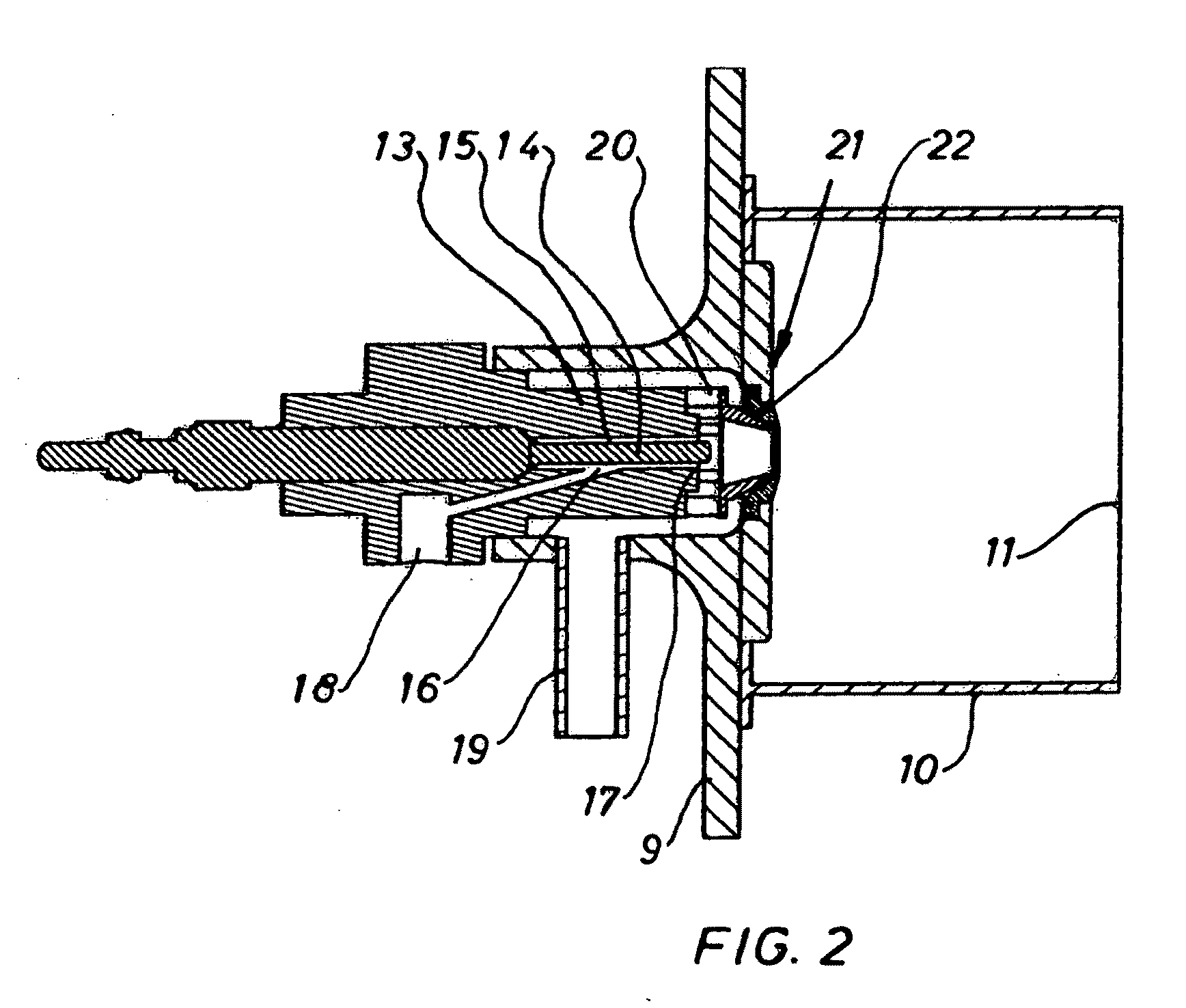
[0005]The present invention provides a fuel nozzle device that has a nozzle body extending at least from an inlet to an outlet and having a support element arranged in it, which together make up a film-forming fuel feed channel. This fuel film-forming configuration of the fuel feed channel entails the advantage that the fuel that is emerging from or being released at the outlet of the fuel nozzle device is better prepared for being mixed with combustion air than is the case when the fuel emerges from the fuel nozzle device in finely atomized form. In fact, it has been found that the finely atomized fuel reacts much more sensitively to changes in the system during the subsequent mixing and ignition with combustion air. Here, very specific problems occur when the fuel is injected through one or more small tubes into an air-swirl atomizing nozzle. Fundamentally, with such a small tube, the fuel can be atomized (with the above-mentioned disadvantages) through the tube by precisely coordinating the amount of fuel fed through and the flow diameter but, for instance, if the throughput is increased, the risk readily exists that the emerging fuel jet will no longer be (completely) atomized and that at least part of the fuel jet will pass through the air-swirl atomizing nozzle without being atomized. Such a system is unstable in terms of its burning properties. All of these drawbacks are avoided by the embodiment according to the invention.
[0009]In another embodiment of the invention, the section is configured in such a way that the fuel film propagates especially mushroom-like. In this context, it should be pointed out that this applies to the support element that ends in the section and to the support element that extends beyond the section. In this context, the extent of the mushrooming is coordinated with the inlet or with the diameter of the downstream air-swirl atomizing nozzle in such a manner that the fuel cone conmes into contact with the combustion air that has been imparted with a swirling flow, and then it is treated in the air-swirl atomizing nozzle to form a homogeneous mixture by the additional combustion air that enters especially in a second stage of the air-swirl atomizing nozzle. Depending on the configuration of the fuel feed channel (and especially when the support element has a large diameter), it can also be advantageous or necessary to constrict the shape of the fuel film that is being released at the section by designing said section accordingly. In another embodiment of the invention, the cross section of the outlet can be varied. With such an embodiment, the cross section (and thus the film formation) can be corrected relatively easily if the cross section diverges from a prescribed value, for instance, caused by different temperatures (and conceivably by opposing coefficients of expansion of the materials). Here, too, an adaptation can be made to varying amounts of emerging fuel.
[0010]In a refinement of the invention, a heating unit is provided on the fuel nozzle device. Generally speaking, this allows the fuel film to be favorably influenced in the case of higher viscosities. Preferably, the heating unit is designed to evaporate and / or break down the fuel, at least at times. This creates the possibility of igniting the fuel. The heating unit can be integrated into a fuel nozzle housing, especially into the nozzle body. This can be realized by means of at least one glow plug that heats up the nozzle body. With an eye towards quickly and uniformly heating up the nozzle body, however, it is more economical and more effective to configure the heating unit as a (heating) coil that surrounds the nozzle body or that is integrated into it.
[0011]In a refinement of the invention, the heating unit is integrated into the support element, or else the support element itself is a heating unit configured, for instance, as a glow plug. This keeps the construction effort low and the heating unit configured in this manner is more effective than one that heats up the nozzle body. This also reduces the consumption of energy. If the support element—as described above—is configured so as to extend well beyond the outlet, this can be done by using a glow plug that preferably ends in the area of the outlet, so that a further-reaching component is affixed thereto.

Problems solved by technology

Here, very specific problems occur when the fuel is injected through one or more small tubes into an air-swirl atomizing nozzle.
Fundamentally, with such a small tube, the fuel can be atomized (with the above-mentioned disadvantages) through the tube by precisely coordinating the amount of fuel fed through and the flow diameter but, for instance, if the throughput is increased, the risk readily exists that the emerging fuel jet will no longer be (completely) atomized and that at least part of the fuel jet will pass through the air-swirl atomizing nozzle without being atomized.
Such a system is unstable in terms of its burning properties.

Method used


Image

  • Exhaust-gas after-treatment system for an auto-ignition internal combustion engine
  • Exhaust-gas after-treatment system for an auto-ignition internal combustion engine
  • Exhaust-gas after-treatment system for an auto-ignition internal combustion engine

Examples


Embodiment Construction

[0022]An internal combustion engine 1 in the embodiment shown is a 4-cylinder auto-ignition internal combustion engine 1 that can be equipped with a common-rail injection system, with exhaust gas turbocharging and with an exhaust gas return, and which, of course, can have any other desired number of cylinders. In the embodiment shown, combustion air is fed to the internal combustion engine 1 via a fresh gas line system 2, while the fuel is injected directly into the individual cylinder combustion chambers via the fuel injection system. The exhaust gas is discharged into an exhaust gas collector 3, from where it is conveyed to an exhaust-gas after-treatment system 5 via an exhaust-gas line 4.

[0023]The exhaust-gas after-treatment system 5 has a burner 6 and a catalytic converter and / or a particle filter 7. The embodiment shown has a catalytic converter 7a and a particle filter 7b. Fundamentally, all devices and device combinations known to be suitable for exhaust-gas after-treatment c...


PUM


Abstract

An exhaust-gas aftertreatment system (5) for an auto-ignition internal combustion engine, having a catalytic converter (7a) and / or particle filter (7b) which are / is assigned a burner (6) arranged upstream in an exhaust line (4), to which burner (6) fuel can be supplied via a fuel nozzle device and also combustion air can be supplied, and wherein the combustion air and the fuel emerging from the fuel nozzle device are mixed in a downstream air swirl vaporizer nozzle (21). An exhaust-gas aftertreatment system (5) having a burner (6) is provided which operates reliably with a compact design and in which the supplied energy for operating the burner (6) is reduced in relation to known systems. Furthermore, the exhaust-gas aftertreatment system (5) can be used for all conceivable variants of a system of said type. This is achieved in that the fuel nozzle device has a nozzle body (13) which extends at least from an inlet (16) to an outlet (17) and which has arranged therein a support body (14), which nozzle body (13) and support body (14) together produce a film-forming fuel supply duct (15).

Description

[0001]The invention relates to an exhaust-gas after-treatment system, especially for an auto-ignition internal combustion engine, having a catalytic converter and / or a particle filter that is / are installed in a housing and that is / are associated with a burner arranged upstream in an exhaust-gas line to which fuel and also combustion air can be fed via a fuel nozzle device, and whereby, in an air-swirl atomizing nozzle located downstream, the combustion air is mixed with the fuel emerging from the fuel nozzle device. Moreover, the invention relates to a method for operating such an exhaust-gas after-treatment system.BACKGROUND[0002]Such an exhaust-gas after-treatment system is disclosed in German patent specification DE 42 42 091 C2. This exhaust-gas after-treatment system, which is configured as a particle filter system, has a burner with a fuel nozzle device that is configured as an atomizing nozzle and that is located upstream from an air-swirl atomizing nozzle in which combustion...

Claims


Application Information

Patent Timeline
Patent Type & Authority Applications(United States)
IPC IPC(8): F01N3/00F01N3/10
CPCF01N3/025F01N3/2033F01N2240/14F23D11/103Y02T10/26F23D2207/00F23D2900/11101F23G7/065F23D11/448Y02T10/12
Inventor MIEBACH, ROLFBROLL, PETERSCHRAML, STEPHAN
Owner DEUTZ AG
Why Eureka
Try Eureka