Refrigerating apparatus

a refrigerating apparatus and refrigerant technology, which is applied in the direction of domestic cooling apparatus, lighting and heating apparatus, insulation of cooling apparatus, etc., can solve the problems of limited refrigerant gasification by the evaporator, insufficient utilization of cooling ability, and evaporation amount of the second refrigerant, so as to reduce the cost of refrigerating apparatus, improve cooling efficiency, and improve the effect of temperature distribution

Inactive Publication Date: 2011-02-03
PANASONIC HEALTHCARE HLDG CO LTD
View PDF10 Cites 34 Cited by
  • Summary
  • Abstract
  • Description
  • Claims
  • Application Information

AI Technical Summary

Benefits of technology

[0019]The present invention has an object to suppress a cost of a refrigerating apparatus while its cooling efficiency is improved and further has an object to improve evenness in temperature distribution inside the refrigerating apparatus while attachment of an evaporation pipe to the apparatus is facilitated.

Problems solved by technology

In the refrigerant circuit, even if the second and third refrigerants are compressed by the compressor and cooled by the condenser, since a temperature of air or the like used for the cooling is high, not an entirety of them will be liquefied and an amount of the refrigerant gasified by the evaporator will be limited, and thus a cooling ability is not sufficiently utilized.
Therefore, problems may arise such as evaporation amounts of the second refrigerant and the third refrigerant of lower evaporation temperatures is not sufficiently obtained in the evaporator and the temperature of the evaporator is not decreased to a desired temperature.
When a tubular evaporation pipe made of metal is to be attached to the boundary portion forming a right angle, it is extremely difficult to bend the evaporation pipe at a right angle while bringing the pipe into thermal contact with the portion and maintaining a constant conductance.
However, since such a welding process is not easy, there is a problem that a manufacturing cost of the refrigerating apparatus is increased.
However, there is a problem that such a portion which is not in thermal contact causes uneven temperature distribution inside the storage and the bending process is not easy.
Thus, the problem of the increased manufacturing cost of the refrigerating apparatus still remains.
Even if the refrigerating apparatus provided with the refrigerant circuit in which the above nonazeotropic refrigerant mixture is sealed is employed, since the evaporation amounts of the second refrigerant and the third refrigerant are not sufficiently obtained, it is difficult to prevent the uneven temperature distribution inside the storage.

Method used


Image

  • Refrigerating apparatus
  • Refrigerating apparatus
  • Refrigerating apparatus

Examples


first embodiment

—Configuration of a Refrigerating Apparatus—

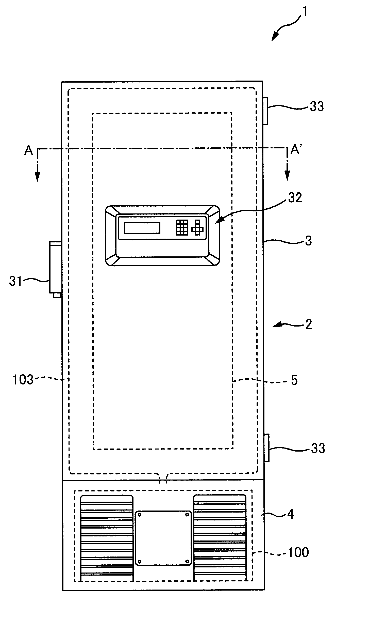
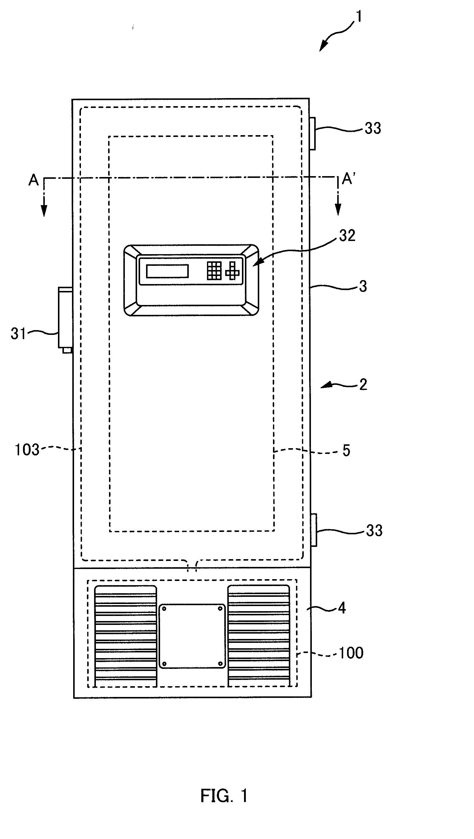
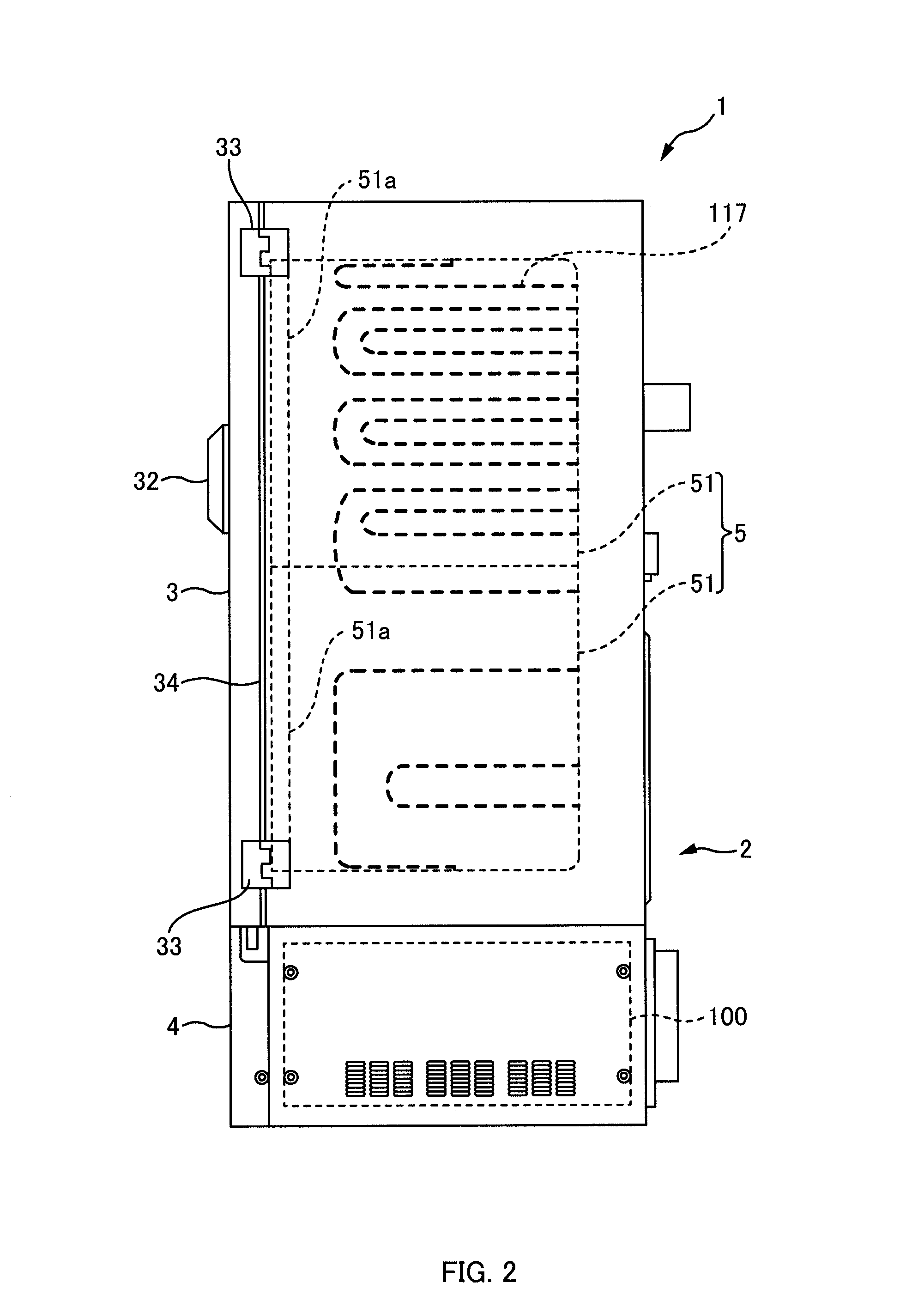
[0040]Referring to FIGS. 1 to 4, a configuration example of the refrigerating apparatus 1 of a first embodiment will be described. FIG. 1 is a front view of an example of a refrigerating apparatus 1 of the first embodiment. FIG. 2 is a side view of the refrigerating apparatus 1 of FIG. 1. FIG. 3 is a sectional view taken along A-A′ in the refrigerating apparatus of FIG. 1. FIG. 4 is a circuit diagram of the example of a refrigerant circuit 100 of the first embodiment.

[0041]As exemplified in FIGS. 1 to 3, the refrigerating apparatus 1 of this embodiment is provided with the refrigerant circuit 100. In the exemplification in the figure, except for an evaporator 117, which will be described later, the refrigerant circuit 100 is mostly housed in a machine chamber 4 in an outer box (housing) 2.

[0042]The outer box 2 is a substantially rectangular parallelepiped box made of steel plate, for example, and houses the machine chamber 4 and an inner b...

second embodiment

—Refrigerating Apparatus—

[0089]In FIGS. 1 to 3, the refrigerating apparatus 1 shall be deemed to be replaced with a refrigerating apparatus 700, the refrigerant circuit 100 shall be deemed to be replaced with a refrigerant circuit 200, the piping 103 shall be deemed to be replaced with a frame pipe 500, and the evaporator 117 shall be deemed to be replaced with an evaporator 600. The other configurations of the refrigerating apparatus 700 in the second embodiment are the same as the configurations of the first embodiment.

—First Refrigerant Circuit and Second Refrigerant Circuit—

[0090]Referring to FIG. 6, a configuration example of the refrigerant circuit 200 of the second embodiment will be described. This figure is a circuit diagram of an example of the refrigerant circuit 200 of the second embodiment.

[0091]As exemplified in this figure, the refrigerant circuit 200 has substantially the same two refrigerant circuits (the respective refrigerant circuits are substantially the same ci...

third embodiment

[0117]A low-temperature storage for storing a storage target such as a refrigerated articles, provided with a vacuum insulation panel and a foam insulation material inside an insulation door so as to improve insulation in the storage is known. Specifically, two sheets of the vacuum insulation panel with substantially the same size are attached to an upper side and a lower side on an inner face of an outer plate of the insulation door. Also, the foam insulation material is filled in a portion between the outer plate and the inner plate of the insulation door except the vacuum insulation panel (Japanese Patent Laid-Open No. H10-300330).

[0118]If air is cooled, a density of the air is naturally raised. Thus, in the low-temperature storage, a temperature of the air at a lower side can be lower than a temperature of the air at an upper side. In the case of the above low-temperature storage, since the substantially same vacuum insulation panels are attached to the upper side and the lower ...


PUM


Abstract

A refrigerating apparatus includes a refrigerating cycle including a compressor, a condenser, a flow divider, a first heat exchanger, a second heat exchanger, a decompressing device, and an evaporator. The refrigerant cycle has sealed therein a mixed refrigerant obtained by mixing at least first to third refrigerants with different evaporation temperatures. The first heat exchanger and the second heat exchanger each includes a double pipe to form a first flow passage in an inner pipe of the double pipe, a second flow passage in an outer pipe of the double pipe, and an intermediate port in a piping connecting between the second flow passage of the first heat exchanger and the second flow passage of the second heat exchanger. A high-temperature and high-pressure refrigerant discharged from the compressor is cooled by the condenser to liquefy the first refrigerant having a high evaporation temperature into a liquid refrigerant.

Description

CROSS-REFERENCE TO RELATED APPLICATIONS[0001]This is a continuation application of International Patent Application No. PCT / JP2009 / 064594 filed Aug. 20, 2009, which claims the benefit of priority to Japanese Patent Application No. 2008-232495 filed Sep. 10, 2008. The full contents of the International Patent Application are incorporated herein by reference.BACKGROUND OF THE INVENTION[0002]1. Field of the Invention[0003]The present invention relates to a refrigerating apparatus.[0004]2. Description of the Related Art[0005]A refrigerating apparatus provided with a refrigerant circuit having a compressor, a condenser, an evaporator, and a heat exchanger in which nonazeotropic refrigerant mixture having a first refrigerant and second and third refrigerants with boiling points (evaporation temperatures) lower than a boiling point of the first refrigerant is sealed is known (e.g., see Japanese Patent Laid-Open No. 2003-13049).[0006]The first refrigerant has, for example, a boiling point a...

Claims


Application Information

Patent Timeline
Patent Type & Authority Applications(United States)
IPC IPC(8): F25B1/00F25B39/02
CPCF25B9/006F25D17/047F25B7/00F25D23/061F25D2201/14F25D23/025F25B1/00C09K5/04F25D11/04F28D1/0426
Inventor KOBAYASHI, SUSUMUYUZAWA, JIROOKUDA, SATOSHISHINYA, HIDETOSHISAGA, TADAHISA
Owner PANASONIC HEALTHCARE HLDG CO LTD
Why Eureka
Try Eureka