Plasma apparatus using a cylinder head

a technology of cylinder head and cylinder head, which is applied in the direction of mechanical equipment, electric ignition installation, machines/engines, etc., can solve the problems of increasing the time required to design an engine, and not allowing the sharing of parts with existing internal combustion engines, so as to promote combustion

Inactive Publication Date: 2011-02-03
MAGINEERING INC
View PDF2 Cites 18 Cited by
  • Summary
  • Abstract
  • Description
  • Claims
  • Application Information

AI Technical Summary

Benefits of technology

[0023]This makes it possible that the electromagnetic wave pulse irradiates the plasma generated by the discharge at the electrode from the antenna near plasma. T

Problems solved by technology

These modifications increase the time required to design an engine, and do

Method used


Image

  • Plasma apparatus using a cylinder head
  • Plasma apparatus using a cylinder head
  • Plasma apparatus using a cylinder head

Examples


Embodiment Construction

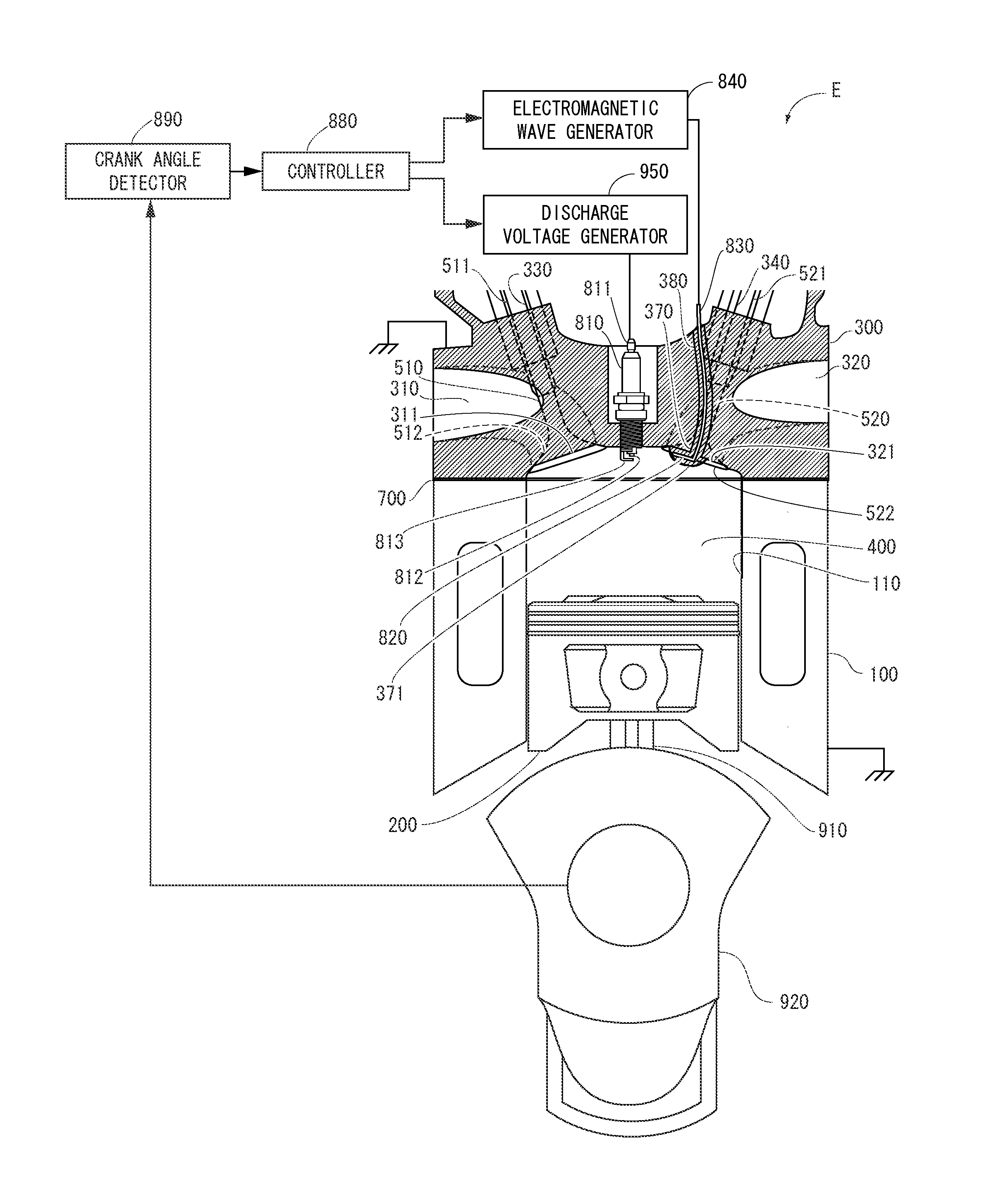
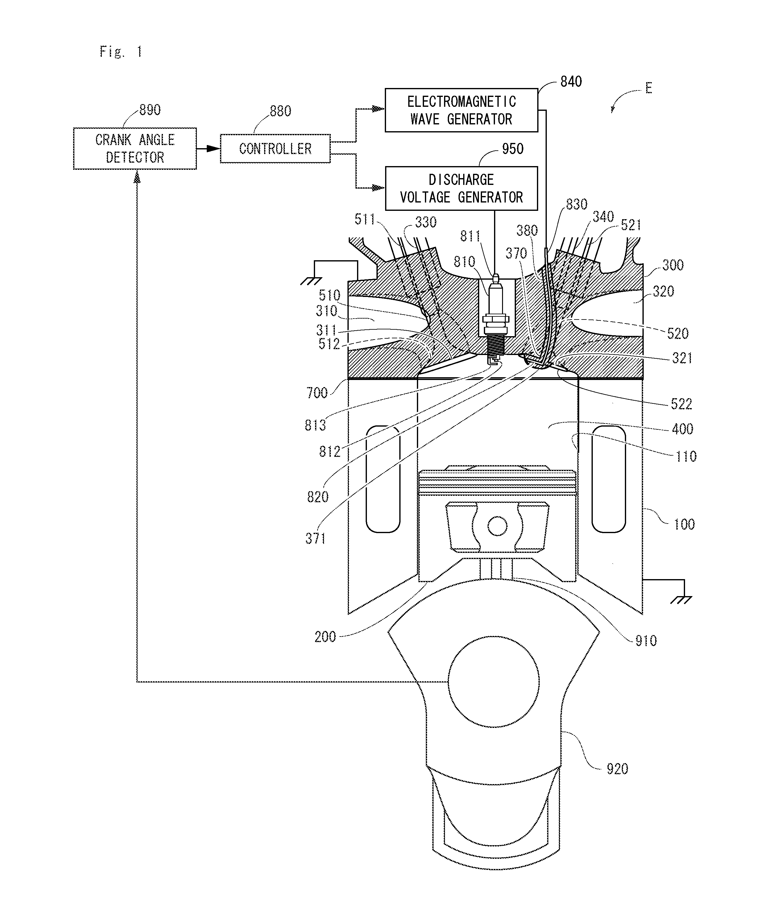
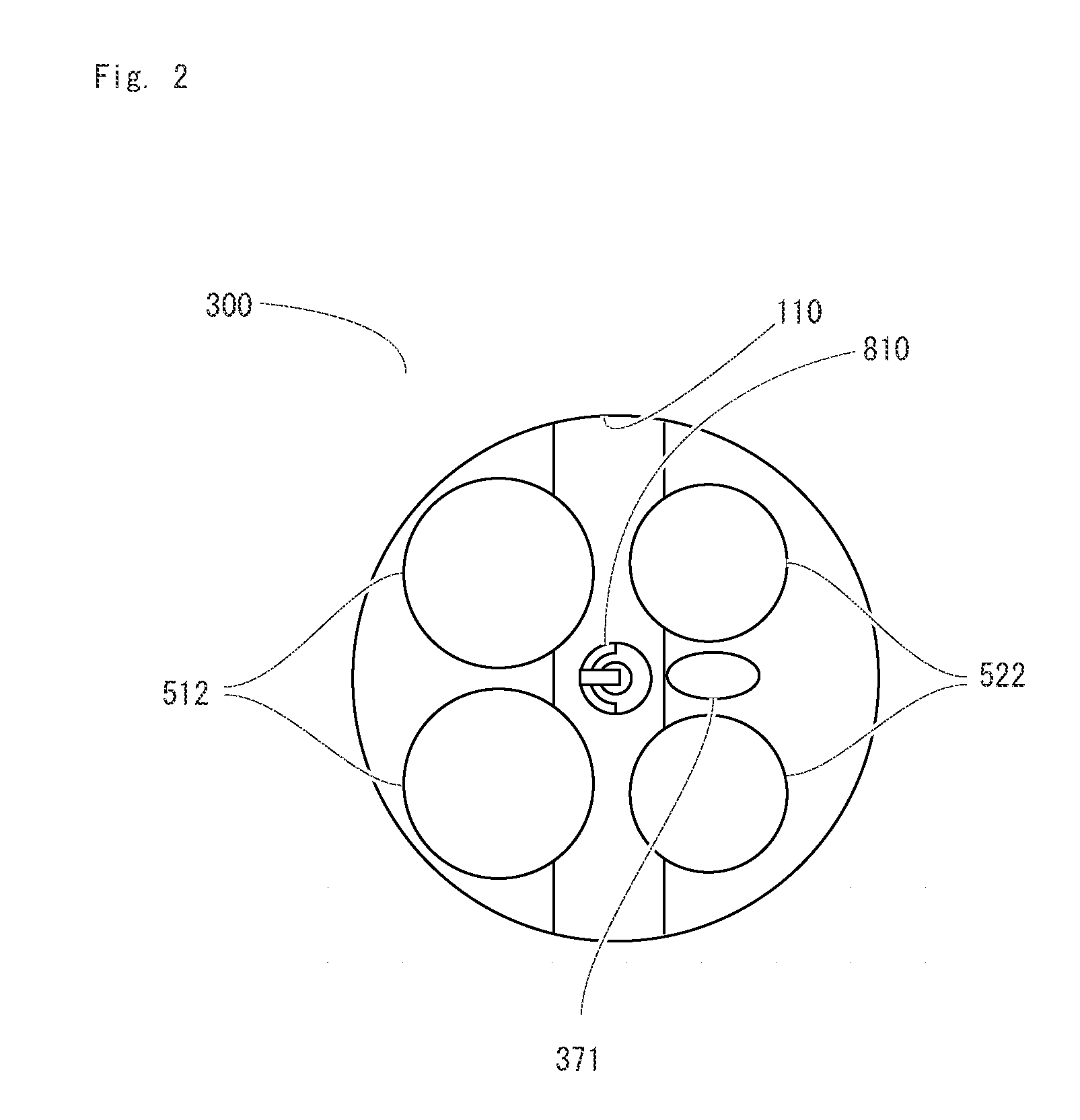
[0040]Hereinafter, embodiments of the present invention will be described. FIGS. 1 and 2 shows the embodiment of the internal combustion engine E comprising the plasma apparatus using a cylinder head of the present invention. The present invention targets reciprocating engines. In this embodiment, engine E is a four-cycle gasoline engine. Item 100 is the cylinder block. Cylinder block 100 contains cylinder 110, which has an approximately circular cross section. Cylinder 110 penetrates cylinder block 100. Piston 200, which has an approximately circular cross section corresponding to cylinder 110, fits into cylinder 110 and reciprocates freely. Cylinder head 300 is assembled on the anti-crankcase side of cylinder block 110. Cylinder head 300, piston 200, and cylinder 110 form combustion chamber 400. Item 910 is a connecting rod, with one end connected to piston 200 and the other end connected to crankshaft 920, which is the output shaft. Cylinder head 300 has intake port 310, which is...


PUM


Abstract

Provided is a plasma apparatus using a cylinder head, which comprises a discharge device installed with an electrode exposed to the combustion chamber and installed in the cylinder head, an antenna installed to protrude from the cylinder head into the combustion chamber, a bulging portion bulging from the cylinder head to the combustion chamber so as to cover the antenna, made from insulator or dielectric, an electromagnetic wave transmission line installed in the cylinder head and with one end connected to the antenna and the other end, covered with insulator or dielectric, penetrating the cylinder head to extend to an outer wall of the cylinder head, and an electromagnetic wave generator for feeding electromagnetic waves to the electromagnetic wave transmission line. At compression stroke, discharge is generated with the electrode of the discharge device and the electromagnetic waves, fed from the electromagnetic wave generator through the electromagnetic wave transmission line, are radiated from the antenna.

Description

TECHNICAL FIELD[0001]This invention belongs to the technical field of the internal combustion engine, and relates to the improvement of combustion in the combustion chamber of an internal combustion engine with a cylinder head.BACKGROUND OF THE INVENTION[0002]Patent Document 1 shows an internal combustion engine including a combustion / reaction chamber, auto-ignition means, microwave radiation means, and control means. The combustion / reaction chamber consists of a cylinder and piston. The combustion / reaction chamber is supplied with a mixture of reactive and oxidation gas. In the combustion / reaction chamber, a plasma reaction of the mixture is carried out. The auto-ignition means automatically ignites the mixture by injecting a mixture of reactive and oxidation gas under high pressure, compressing the mixture and increasing the temperature. The microwave radiation means radiates the combustion / reaction chamber with microwaves. The control means controls the auto-ignition means and mi...

Claims


Application Information

Patent Timeline
IPC IPC(8): H05H1/24
CPCF02B23/08F02P23/04F02P23/045F02P9/007Y02T10/125Y02T10/12
Inventor IKEDA, YUJI
Owner MAGINEERING INC
Why Eureka
Try Eureka