Check patentability & draft patents in minutes with Patsnap Eureka AI!

Signal Processing Circuit

Active Publication Date: 2011-02-03
MEDIATEK INC
View PDF7 Cites 0 Cited by
  • Summary
  • Abstract
  • Description
  • Claims
  • Application Information

AI Technical Summary

Benefits of technology

[0009]Therefore, one object of the present invention is to provide a mixer capable of improving linearity of the mixer, reducing influences of DC offset, and increasing an input signal swing.

Problems solved by technology

However, when a swing of the baseband signal is beyond a predetermined range, a transconducting circuit cannot linearly convert the signal from a voltage form to a current form.
In a differential system, semiconductor manufacturing process variations results in size mismatch between two corresponding transconducting components and thereby incurring a direct current (DC) offset, which then induces local oscillator (LO) leakage.
The LO leakage may lead to deterioration in a receive quality of a communication system.
As a result a DC offset is incurred that induces an LO leakage in an LO signal generated at an output end of the mixer 100, such that a receive quality of a communication system is undesirably affected.

Method used


Image

  • Signal Processing Circuit
  • Signal Processing Circuit
  • Signal Processing Circuit

Examples


Embodiment Construction

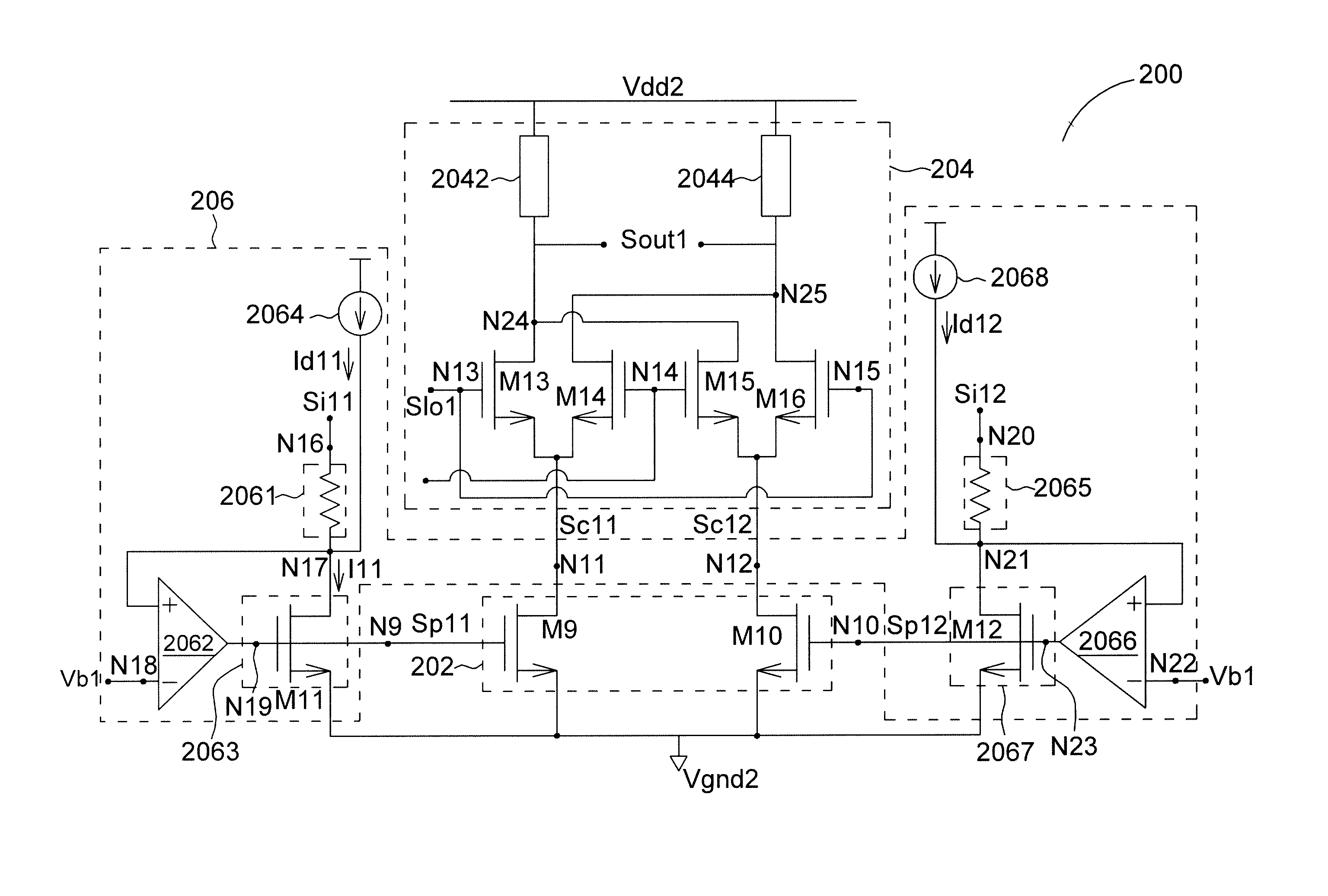
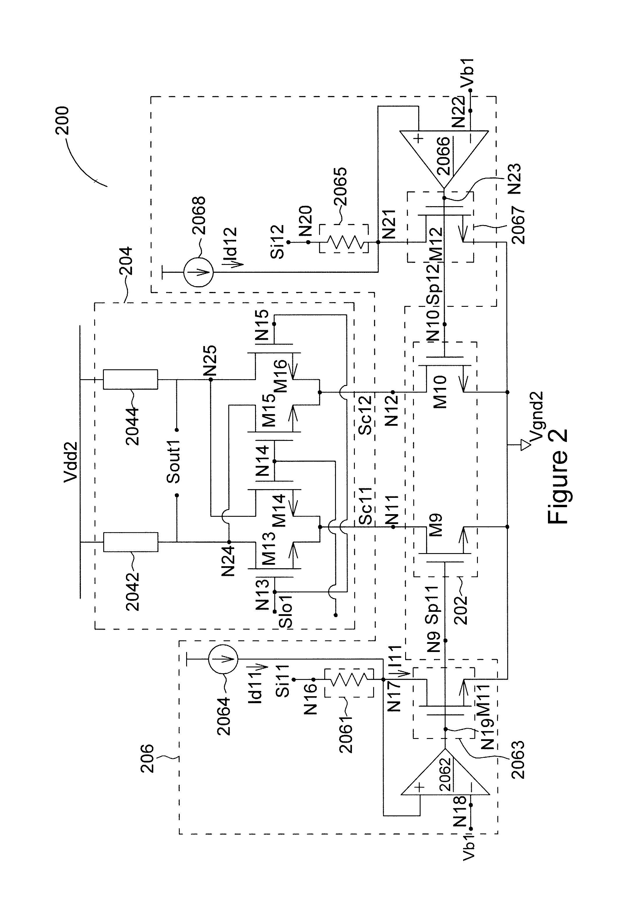
[0021]FIG. 2 shows a mixer 200 in accordance with an embodiment of the present invention. It is to be noted that, in order to illustrate the spirit of the present invention, the mixer 200 is represented by a differential form; however, it shall not be construed as limiting the present invention. The mixer 200 comprises a transconductance circuit 202, a converting circuit 204, and a differential circuit 206. The transconductance circuit 202 has input ends N9 and N10 for respectively converting a first voltage signal Sp11 and a second voltage signal Sp12 to a first current signal Sc11 and a second current signal Sc12, and output ends N11 and N12 for respectively outputting the first current signal Sc11 and the second current signal Sc12. The transconductance circuit 201 comprises N-type FETs M9 and M10, and connections between the FETs are as shown in FIG. 2. The converting circuit 204 coupled to the output ends N11 and N12 of the transconductance circuit 202 comprises input ports N13...


PUM


Abstract

A signal processing circuit includes a differential input circuit, a first DC filter, a second DC filter, a differential transconductance circuit, and a differential converting circuit. The differential input circuit includes first and second input circuits respectively for receiving first and second input signals to generate first and second processed signals. The first DC filter and the second DC filter, respectively coupled to the first and the second input circuits, receive the first and the second processed signals and output first and second voltage signals. The differential transconductance circuit includes first and second transconductance circuits, respectively coupled to the first and the second DC filters, for converting the first and the second voltage signals to first and second current signals. The differential converting circuit includes first and second converting circuits, respectively coupled to the first and the second transconductance circuits, for mixing the first and the second current signals with first and second clock signals to generate first and second output signals.

Description

CROSS REFERENCE TO RELATED PATENT APPLICATION[0001]This patent application is based on Taiwan, R.O.C. patent application No. 098125885 filed on Jul. 31, 2009.FIELD OF THE INVENTION[0002]The present invention relates to a mixer, and more particularly, to a mixer capable of increasing a swing of an input signal and reducing an offset signal.BACKGROUND OF THE INVENTION[0003]In the wireless communication field, a mixer up-converts a baseband signal to a radio frequency signal by mixing the baseband signal with a high frequency (HF) clock, or down-converts a received signal to a baseband signal for subsequent signal processing. However, when a swing of the baseband signal is beyond a predetermined range, a transconducting circuit cannot linearly convert the signal from a voltage form to a current form.[0004]In a differential system, semiconductor manufacturing process variations results in size mismatch between two corresponding transconducting components and thereby incurring a direct c...

Claims


Application Information

Patent Timeline
IPC IPC(8): H03F3/45
CPCH03F3/45183H03F3/45636H03F2200/375H03F2203/45418H03F2203/45318H03F2203/45356H03F2203/45366H03F2200/78
Inventor HSU, WEI-HSIUHSIAO, SHUO YUAN
Owner MEDIATEK INC
Features
  • R&D
  • Intellectual Property
  • Life Sciences
  • Materials
  • Tech Scout
  • Unparalleled Data Quality
  • Higher Quality Content
  • 60% Fewer Hallucinations
Learn More