Inertial Sensor Kinematic Coupling

a technology of kinematic coupling and sensor, applied in the field of motion tracking system, can solve the problems of occlusion of camera system, inability to track the motion of an object in volume, and inability to accurately estimate the distance between joints linking the object parts, etc.

Inactive Publication Date: 2011-02-03
XSENS HLDG BV
View PDF5 Cites 69 Cited by
  • Summary
  • Abstract
  • Description
  • Claims
  • Application Information

AI Technical Summary

Benefits of technology

[0011]It is a further object of the invention to provide a system in which the distance between the joints linking

Problems solved by technology

However, such optical measuring systems can only track the motion of an object in the volume which is recorded with the cameras.
Moreover, a camera system suffers from occlusion when the view of the camera of the object is obstructed by another object, or when one or more cameras perform poorly, e.g., due to light conditions.
While such magnetic systems do not suffer from occlusion and will work in any light condition, they are nonetheless relatively sensitive to magnetic disturbances.
Further, these systems need relatively large transmitters due to the rapid decrease in magnetic field strength over distance.
However, such systems lack the capability to provide an orientation with respect to an external reference system, e.g., earth.
Moreover, the mechanical coupling to the body of interest is cumbersome.
While systems based on ultra-sonic sensors do not share all of the above problems, they are prone to disturbances such as temperature and humidity of the air as well as wind and other ultra-sonic sources.
In addition, the range of such systems is often relatively limited and thus the amount of installed infrastructu

Method used


Image

  • Inertial Sensor Kinematic Coupling
  • Inertial Sensor Kinematic Coupling
  • Inertial Sensor Kinematic Coupling

Examples


Embodiment Construction

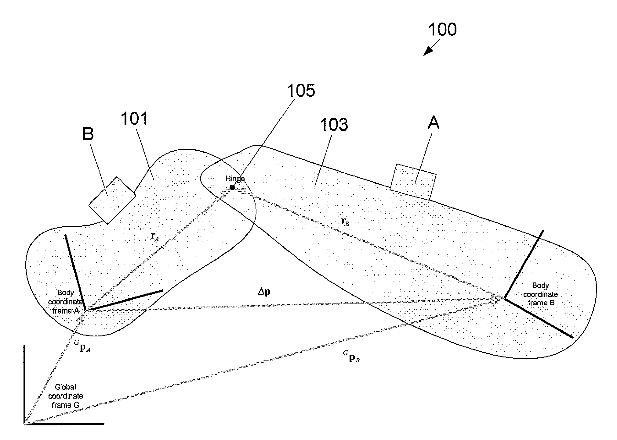
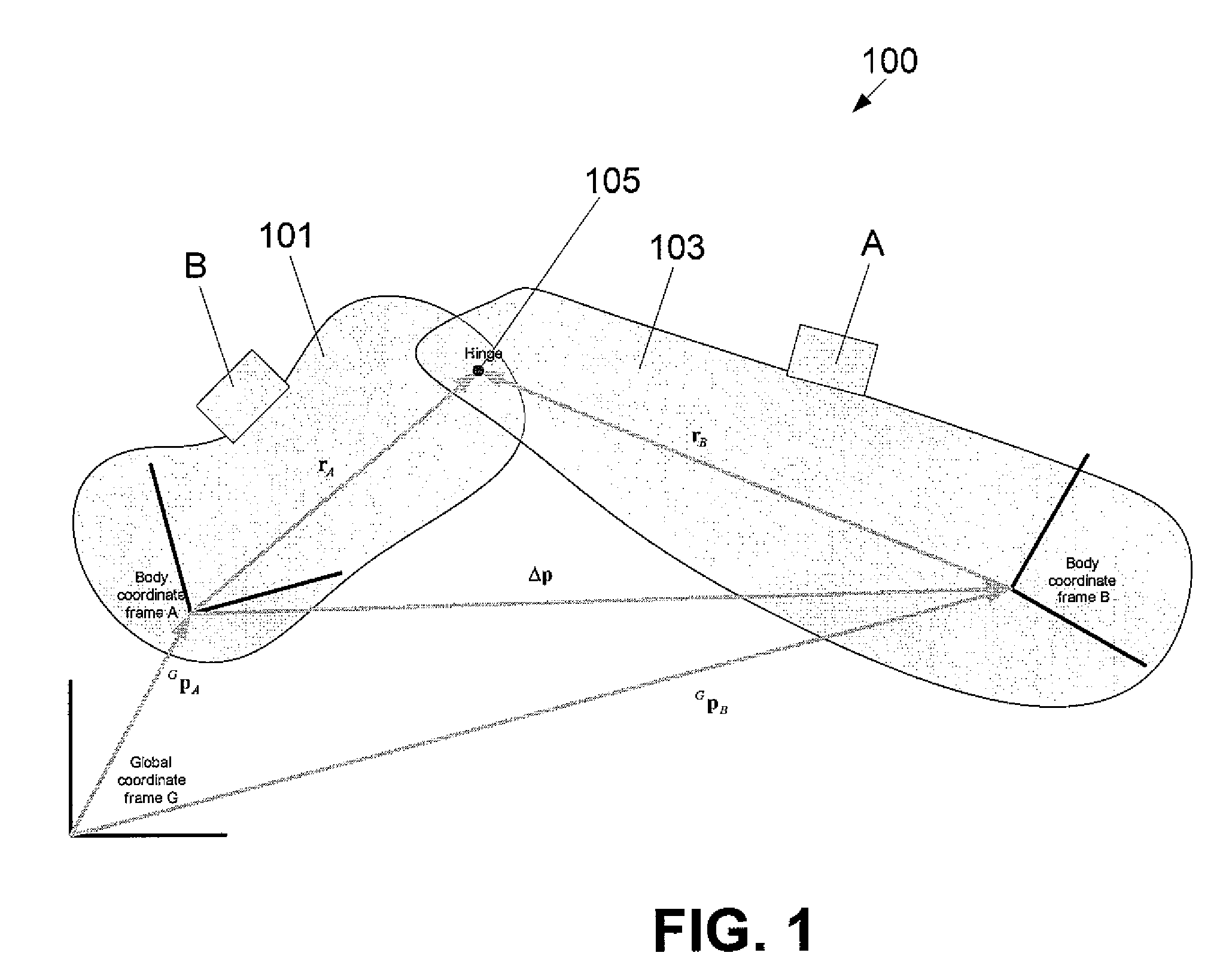
[0025]The kinematic coupling (KiC) algorithm calculates (relative) orientation of two segments on each side of a joint. An inertial measurement unit aka IMU (3D accelerometer, 3D gyroscope, optionally equipped with a 3D magnetometer) is rigidly attached to each body segment. Only limited a-priori knowledge about the joint connection is needed to accurately determine the joint angle. This relative orientation between the two segments is essentially determined without using the local magnetic field as a reference for heading but using information derived from the joint acceleration.

[0026]The following initial assumptions are made:[0027]rA en rB, the joint expressed in the sensor frame A and B, respectively, are fixed.[0028]The Global frame is defined by X pointing to the north, Y pointing to the west and Z pointing up.[0029]The acceleration and angular velocity of segment A and segment B are measured by the sensors attached to these segments.[0030]The initial sensor orientations are c...


PUM


Abstract

A method is disclosed for measuring the motion of an object, composed of multiple segments connected by joints, via the estimation of the 3D orientation of the object segments relative to one another without dependence on a magnetic field as a reference for heading. The method includes first applying a plurality of inertial sensor units to the segments of the object, e.g., a user thigh, shank, foot, etc. Next an approximation of the distance between each inertial sensor unit and at least one adjacent joint is provided and the joint is subjected to an acceleration, e.g., as the user takes a step or two. The relative orientations of the segments are calculated and the orientations are used to form an estimation of the 3D orientation of the object segments relative to one another without using the local magnetic field as a reference for heading.

Description

FIELD OF THE INVENTION[0001]The invention relates to a motion tracking system for tracking an object composed of object parts, connected by joints, in a three-dimensional space, and in particular, to a motion tracking system for tracking the movements of a human body.BACKGROUND OF THE INVENTION[0002]Measurement of motion with a high resolution is important for many medical, sports and ergonomic applications. Further, in the film and computer game market, there is a great need for motion data for the purpose of advanced animation and special effects. Additionally, motion data is also important in Virtual Reality (VR) and Augmented Reality (AR) applications for training and simulation. Finally, real-time 3D motion data is of great importance for control and stabilization of robots and robotic devices.[0003]There are a number of technologies available for tracking and recording 3D motion data. They generally require that an infrastructure be constructed around the object to be tracked....

Claims


Application Information

Patent Timeline
IPC IPC(8): A61B5/11
CPCA61B5/1038A61B5/1114A61B5/1121A61B5/1126A61B5/6829A61B2562/0219A63F2300/105G01C21/16A61B5/6828A61B5/4528
Inventor LUINGE, HENDRIK JOHANNESROETENBERG, DANIELSLYCKE, PER JOHAN
Owner XSENS HLDG BV
Why Eureka
Try Eureka