Continuous casting machine for forming a lead alloy strip of large thickness

a technology of lead alloy and casting machine, which is applied in the field of continuous casting machine for forming lead alloy strips of large thickness, can solve the problems of high construction complexity, limited width of lead strips which it is able to produce, and excessive power consumption for rotation, so as to achieve optimum mechanical and chemical properties, reduce production costs, and ensure the effect of quality

Inactive Publication Date: 2011-02-10
SOVEMA
View PDF13 Cites 15 Cited by
  • Summary
  • Abstract
  • Description
  • Claims
  • Application Information

AI Technical Summary

Benefits of technology

[0031]Owing to this machine it is possible to produce at a low cost and with a high production output a continuous lead alloy strip which has optimum mechanical and chemical properties.
[0032]The machine according to the invention is at the same time constructionally simple and operationally entirely reliable.

Problems solved by technology

The main drawback of this machine consists in its high constructional complexity.
Moreover, the temperature of the rolls must be regulated in an extremely precise manner in order to allow the strip to leave the rolls completely solidified without, however, an excessive cooling causing occlusion of the through-slit between the rolls or an excessive power consumption for rotation thereof.
The main drawback of this machine of the known type consists in the limited width of the lead strips which it is able to produce.
Moreover, an excessive rigidity of the metal strip results in considerable difficulties for rotation thereof on the transmission rolls.
The machines described in the aforementioned U.S. Pat. No. 5,462,109 and U.S. Pat. No. 5,948,566 are intended for the production of strips of very limited thickness, typically of the order of a millimeter, and do not allow the production of strips which have a thickness greater than two millimetres nor those with a large thickness.
Consequently, these machines are entirely unsuitable for the production of strips which are to be rolled with a high rolling ratio for the formation of lead grids with a high grain refinement of the alloy or with optimum mechanical and corrosion-resistance properties.
Finally, a drawback which is common to all the continuous casting machines of the known type described above consists in the fact that the lead does not solidify with a homogeneous crystal and fine-grain structure suitable for ensuring optimum mechanical and corrosion resistance properties.
For example, in order to increase the number of nuclei present in the molten lead bath, the machines described in the U.S. Pat. No. 5,462,109 and U.S. Pat. No. 5,948,566 envisage pitting the outer cooling surfaces of the drums with glass dust, without however this treatment producing satisfactory results.
In view of the speed of production of the continuous strip, the chemical refining techniques, which envisage adding to the lead alloy particles of other already solid components, called inoculating or refining agents (such as copper, selenium and tin), which act as active nuclei in the liquid metal, have proved to be equally unsatisfactory.
This machine cannot be modified replacing the grooves with an annular seat in order to form a continuous lead strip, since the problem of transporting the lead arranged inside the seat integrally with the drum would still remain entirely unsolved.

Method used


Image

  • Continuous casting machine for forming a lead alloy strip of large thickness
  • Continuous casting machine for forming a lead alloy strip of large thickness
  • Continuous casting machine for forming a lead alloy strip of large thickness

Examples


Embodiment Construction

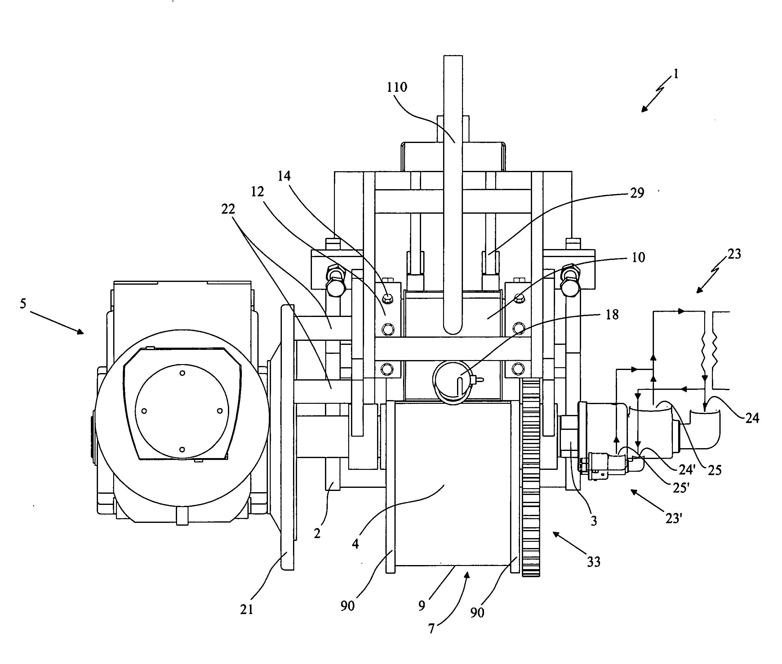
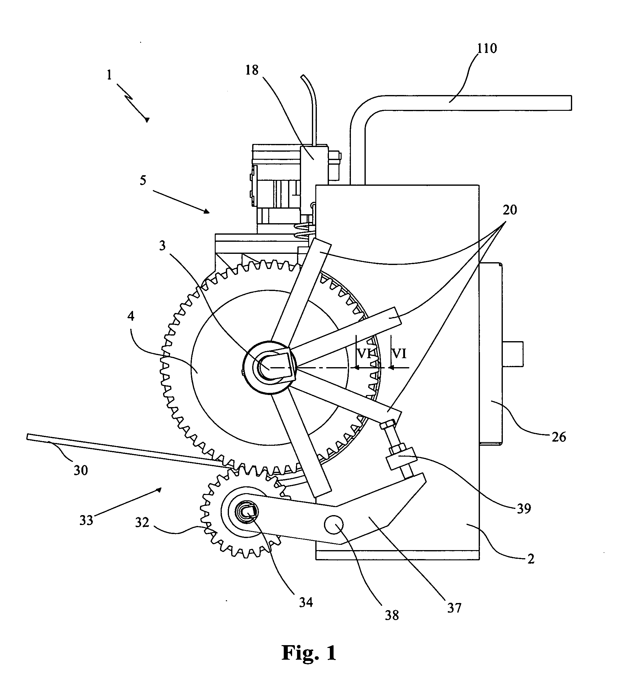
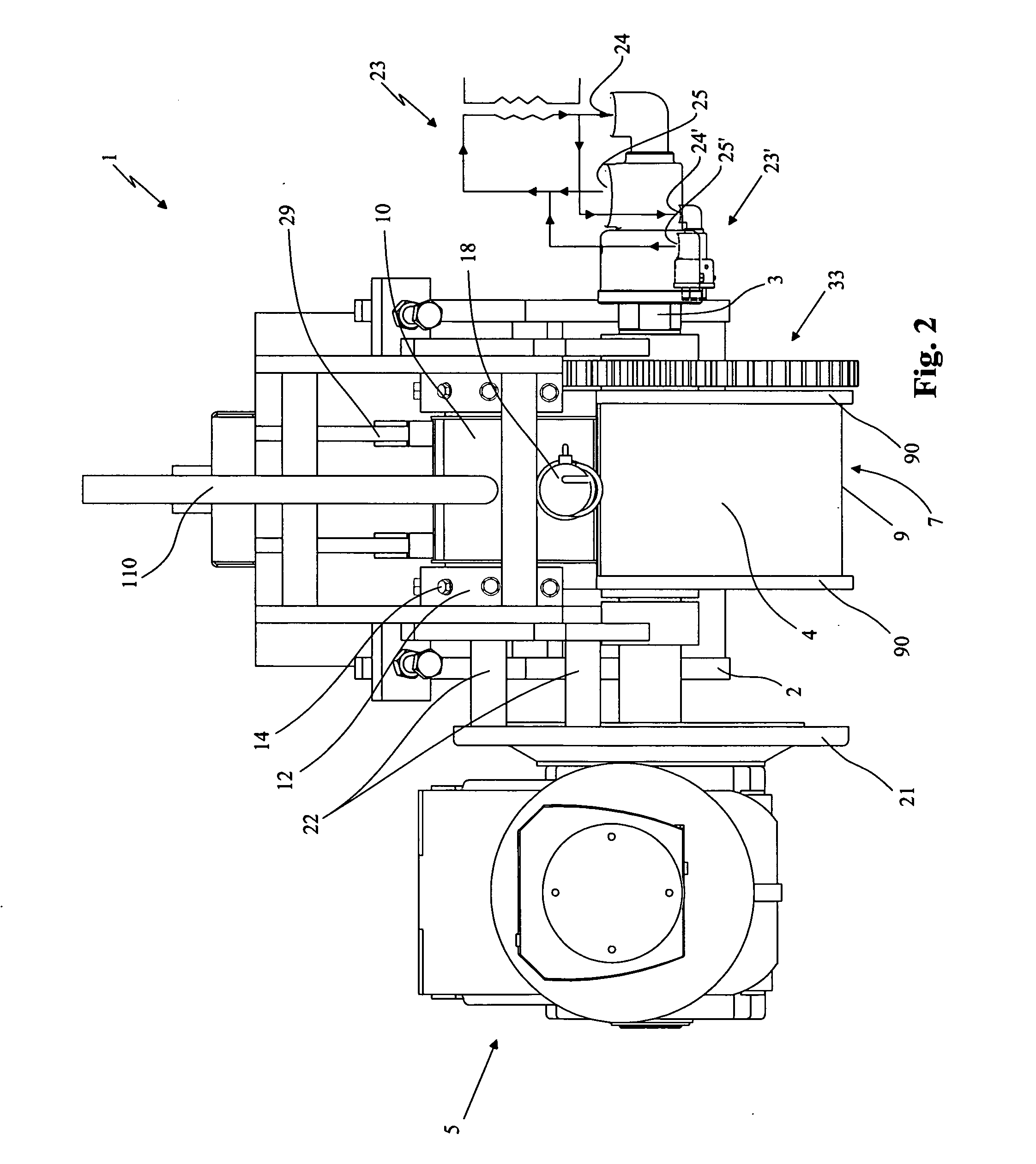
[0040]With reference to the drawings 1 denotes in its entirety the continuous casting machine for forming a lead alloy strip of large thickness according to the present invention.

[0041]The lead strip produced by this machine is advantageously intended to be used in conventional processes for forming lead grids to be used with positive polarity or negative polarity in batteries.

[0042]These processes envisage the use of a large-thickness strip, rolling thereof down to the desired thickness and then, for example, stamping or alternatively incision and expansion thereof in order to form the individual grids.

[0043]Below, in order to simplify illustration, reference shall be made generally to a strip intended to be used in rolling processes for forming grids for electric batteries, and therefore typically with a thickness of 8-18 mm and width of 100-350 mm, described generally as being made of lead, although the material forming the strip may consist of any lead alloy suitable for use in ...


PUM

PropertyMeasurementUnit
thicknessaaaaaaaaaa
thicknessaaaaaaaaaa
thicknessaaaaaaaaaa

Abstract

Continuous casting machine for forming a lead alloy strip of large thickness; which comprises a cooled rotating drum (4) having an annular seat (8) formed on the periphery thereof and a vat (10) for containing a molten lead bath, which is sealingly engaged on the peripheral surface (7) of the rotating drum (4). The machine (1) also comprises a fixed shoe (11) extending, from the vat (10), along an arc (25) around the rotating drum (4) and having an arc shape suitable for sealing engagement, in a sliding relationship, on the shoulders (90) of the annular seat (8). Heating means (26) are provided, these consisting of a plurality of torches acting on the shoe (11) along at least an initial section thereof (25) which extends from the vat (10), for heating to a temperature higher than the melting temperature of the lead alloy the free surface of the lead inside the annular seat (8). The bottom (9) of the annular seat (8) is knurled, while the inner surface (13) of the shoe (11) which slides on the lead is smooth and kept at a high temperature by the heating means (26). As a result of these characteristic features, the rotating drum (4) is able to transport in a rotationally integral manner the lead from a first angular position where it is inserted in the molten state inside the annular seat of the rotating drum (8) to a following angular position where it is extracted in the form of a continuous strip.

Description

CROSS REFERENCE TO RELATED APPLICATIONS[0001]Applicant claims priority under 35 U.S.C. §119 of Italian Patent Application No. PD2009A000237 filed on Aug. 7, 2009.FIELD OF APPLICATION[0002]The present invention relates to a continuous casting machine for forming a lead alloy strip of large thickness.[0003]The machine in question is intended to be used in industrial processes for the production of electric batteries for forming a lead alloy strip of large thickness; this strip is then used in conventional rolling processes for subsequent stamping, incision or expansion operations in order to form the individual grids intended to be used with positive polarity or negative polarity in the batteries.BACKGROUND ART[0004]In the industrial sector relating to the production of electric batteries there exists a particularly pressing need to obtain, by means of low-cost processes, continuous high-quality lead strips which are then used for manufacturing, by means of conventional stamping or ex...

Claims


Application Information

Patent Timeline
Patent Type & Authority Applications(United States)
IPC IPC(8): B22D11/06
CPCB22D11/0634B22D25/04H01M4/72B22D45/00B22D11/114B22D27/00B22D1/007Y02E60/10
Inventor FARINA, PIETRO
Owner SOVEMA
Why Eureka
Try Eureka