Heat Sink Structure

a technology of heat sink and heat sink, which is applied in the direction of heat exchanger fastening, semiconductor devices for light sources, light and heating apparatus, etc., can solve the problems of reducing lighting efficiency, increasing heat produced by leds, and high amount of heat produced by electronic elements, so as to reduce weight and material cost, good heat dissipation effect, and high thermal conductivity

Inactive Publication Date: 2011-02-10
ASIA VITAL COMPONENTSSHEN ZHEN
View PDF22 Cites 27 Cited by
  • Summary
  • Abstract
  • Description
  • Claims
  • Application Information

AI Technical Summary

Benefits of technology

With the heat dissipating body made of a heat-conducting plastic material through injection molding and the heat pipe helically embedded in the plastic heat dissipating body, the heat sink structure of the present invention not only provides high thermal conductivity and good heat dissipating effect, but also has reduced weight and material cost.

Problems solved by technology

As a result, a high amount of heat is also produced by the electronic elements in the electronic information products when they operate at high speed.
However, while the high-current LED provides increased illuminance, the heat produced by the LED is inevitably increased, too.
The produced high amount of heat must be timely removed, lest the heat should accumulate around the LED to cause lowered lighting efficiency and even shortened LED service life.
However, all these electronic apparatuses have the same problem of having relatively poor heat dissipation efficiency, which adversely results in burned-out apparatus due to overheating, increased light wane and shortened service life.
Since both of the heat dissipating body 11 and the radiating fins 12 are made of a metal material, the heat sink structure 1 requires relatively high material cost and is relatively heavy, which form limitations in the applicability of the heat sink structure 1.
In brief, the conventional heat sink structure 1 has the following disadvantages: (1) low heat conductivity; (2) high material cost; and (3) heavy in weight.

Method used


Image

  • Heat Sink Structure
  • Heat Sink Structure
  • Heat Sink Structure

Examples


Embodiment Construction

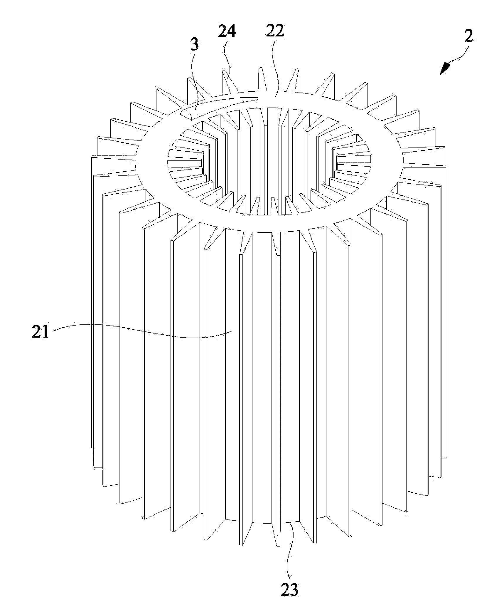
Please refer to FIGS. 3 and 4. A heat sink structure according to a preferred embodiment of the present invention includes a heat dissipating body 2 and a heat pipe 3. The heat dissipating body 2 is made of a plastic material through injection molding, and can be molded into various shapes depending on actual need. The plastic material for molding the heat dissipating body 2 is a heat-conducting material selected from the group consisting of Ethylon (UPE), polyoxymethylene (POM), polyethylene terephthalate (PETP), nylon, polypropylene (PP), polyethylene (PE), polyvinylidene fluoride (PVDF), Teflon (polytetrafluoroethylene or PTFE), polyvinyl chloride (PVC), Acrylonitrile Butadiene Styrene (ABS), tempered glass, polyether polyols (PES), acrylic (polymethylmethacrylate or PMMA), poly(ether-ether-ketone) (PEEK), and poly(amide-imide) (PAI).

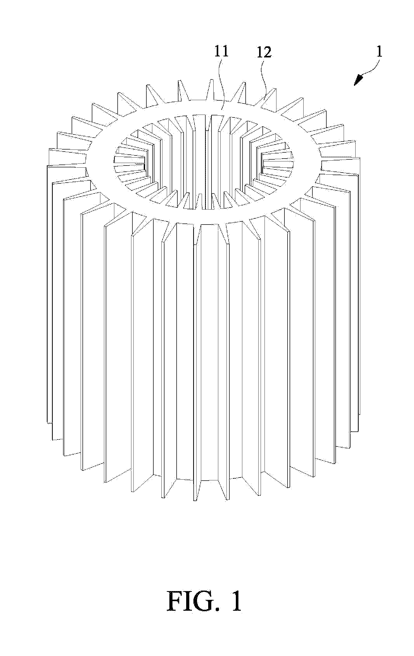
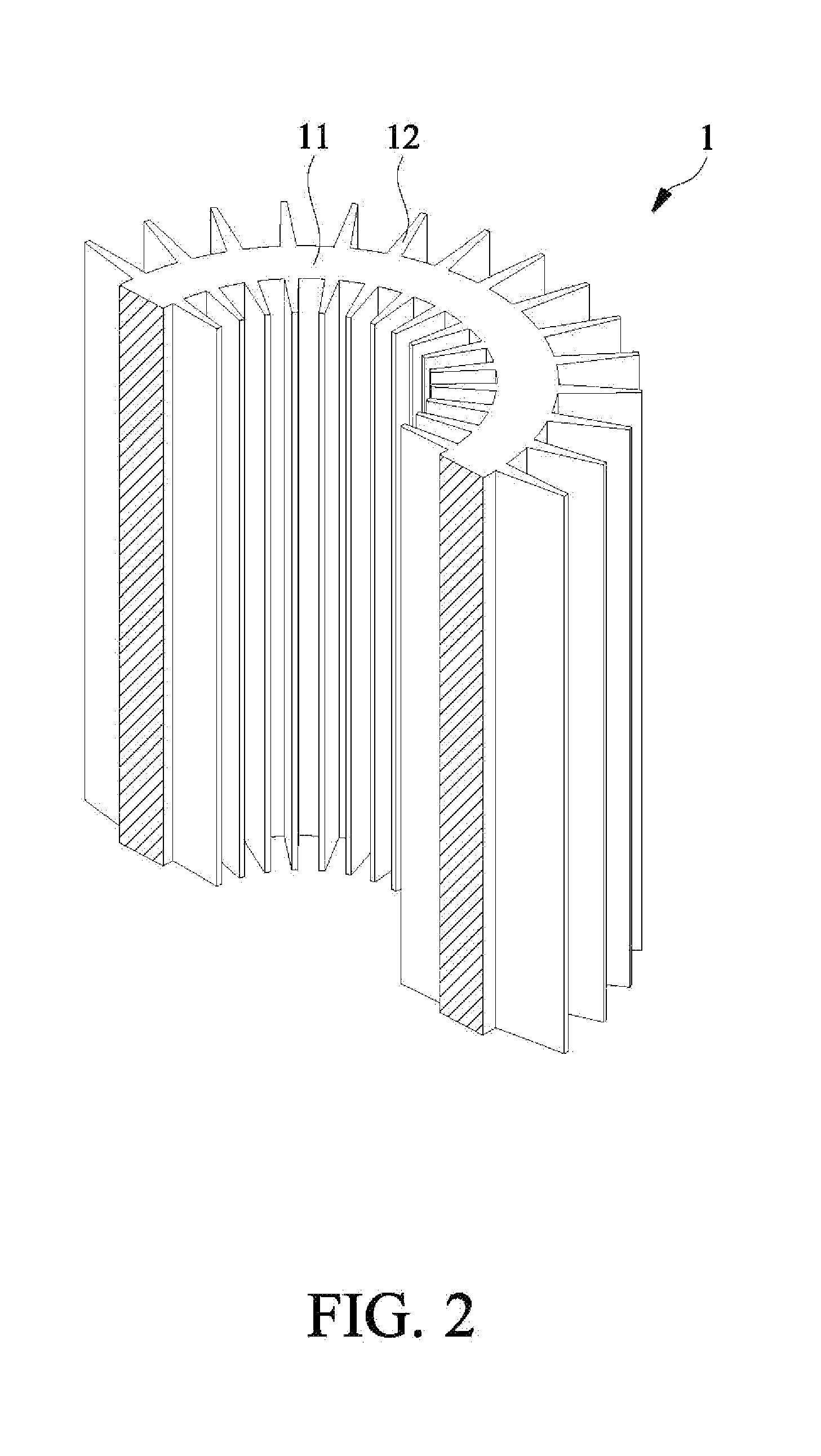
In the illustrated embodiment of the present invention, the heat dissipating body 2 is injection molded into a hollow cylinder including a main body...


PUM

PropertyMeasurementUnit
thermal conductivityaaaaaaaaaa
melting pointaaaaaaaaaa
weightaaaaaaaaaa

Abstract

A heat sink structure includes a heat dissipating body and at least one heat pipe. The heat dissipating body includes a main body having two opposite first and second end faces, and a plurality of radiating fins formed on two wall surfaces of the main body. The heat dissipating body is made of a heat-conducting plastic material through injection molding, and the heat pipe is embedded in the heat dissipating body during the process of injection molding the heat dissipating body. The heat pipe has two opposite first and second ends respectively exposed from the first and second end faces of the heat dissipating body for directly contacting with a heat source, and a pipe body helically extended between the first and second ends and embedded in the heat dissipating body. With these arrangements, the heat sink structure has reduced weight and material cost while providing good heat dissipating effect.

Description

FIELD OF THE INVENTIONThe present invention relates to a heat sink structure, and more particularly to a heat sink structure consisting of a heat dissipating body made of a heat-conducting plastic material and a heat pipe made of a metal material to thereby have reduce weight and material cost while providing good heat dissipating effect.BACKGROUND OF THE INVENTIONVarious kinds of electronic information products, such as computers, have become very popular among consumers and been widely applied in many different fields. Consumers' demands bring prosperous development in the electronic information industry, and all the currently commercially available electronic information products have increasingly upgraded computing speed and expanded access capacity. As a result, a high amount of heat is also produced by the electronic elements in the electronic information products when they operate at high speed.A light emitting diode (LED) emits cold light, and has the advantages of low power...

Claims


Application Information

Patent Timeline
Patent Type & Authority Applications(United States)
IPC IPC(8): F28F13/00
CPCF21K9/00F21V29/773F21Y2101/02F28D7/024F28D15/0233F28D15/0266F28F1/12F28F1/16F28F21/067H01L23/427F21V29/006F28F2275/02H01L2924/0002F21V29/004H01L2924/00F21Y2115/10F21V29/51
Inventor QIN, TENG-ZHILAN, WEN-JI
Owner ASIA VITAL COMPONENTSSHEN ZHEN
Why Eureka
Try Eureka