High pressure charged particle beam system

a particle beam and high-pressure technology, applied in the field of electron microscopes, can solve the problems of affecting the operation of hpsem, affecting the quality of particle beams, and not being suitable for high-vacuum observation of wet samples such as biological specimens, so as to facilitate rapid introduction, exhaustion, and switching

Active Publication Date: 2011-02-10
FEI CO
View PDF45 Cites 53 Cited by
  • Summary
  • Abstract
  • Description
  • Claims
  • Application Information

AI Technical Summary

Benefits of technology

[0018]Embodiments of the invention include a cell in which the sample is positioned during high pressure charged particle beam processing. The cell reduces the amount of gas required for processing, thereby allowing rapid introduction, exhaustion, and switching between gases and between processing and imaging modes. Some embodiments include one or more gas inlets and a gas outlet connected to further facilitate rapid introduction, exhaustion, and switching between gases in the cell. Gas inlets may include one or more valves to rapidly select among multiple gas sources. In some embodiments, the cell is positioned within a sample chamber of a HPSEM. Maintaining the processes gases within the cell protects the sample chamber and column from contact with the gases. In some embodiments, the cell takes the place of the sample chamber. In some embodiments, the temperature of the cell walls and the sample can be controlled.

Problems solved by technology

However, wet samples such as biological specimens are not suitable for observation in a high vacuum.
Such samples experience evaporation of their fluid content in the vacuum before an accurate image can be obtained, and the evaporated gas interferes with the primary electron beam.
While an HPSEM can observe moist biological sample, problems still exist with such observations.
Such condensation can interfere with the operation of HPSEM, as well as cause corrosion and contamination.
Conventional HPSEMs are not well adapted for efficient beam chemistry.
One problem with using a HPSEM system for beam chemistry is the considerable time required to introduce and evacuate gases from the sample chamber.
It takes a considerable amount of time for the gas to reach an equilibrium pressure, particularly if the vapor pressure of the beam chemistry precursor is similar to the desired operating pressure of the sample chamber.
This problem is compounded when a process entails injecting multiple process gases into the sample chamber.
The pressure gauge measures the total pressure in the sample chamber and is incapable of separately measuring the partial pressures of multiple process gases in a mixture.
Thus, it is difficult to know when the desired partial pressure of each of the gases has been achieved.
If some process gas remains in the chamber during imaging, the sample may be unintentionally modified by the beam during the imaging operation.
Because of the considerable time required to fully evacuate one gas and then to reach equilibrium pressure with another gas, such multiple step operations are not practical in an HPSEM.
The time is further increased in some cases because the molecules of some gases used in beam chemistry tend to have very long adsorption times on the vacuum chamber walls, and take longer to fully evaporate.
Another reason why HPSEMs are not generally used for beam chemistry is that corrosive process gases can degrade the HPSEM components.
For example, certain process gases associated with beam chemistry can react spontaneously with plastic tubing and are very dangerous to human health.
A gas like XeF2 can make plastic gas tubing brittle and eventually cause leaks of dangerous gases into the surrounding environment.

Method used


Image

  • High pressure charged particle beam system
  • High pressure charged particle beam system
  • High pressure charged particle beam system

Examples


Embodiment Construction

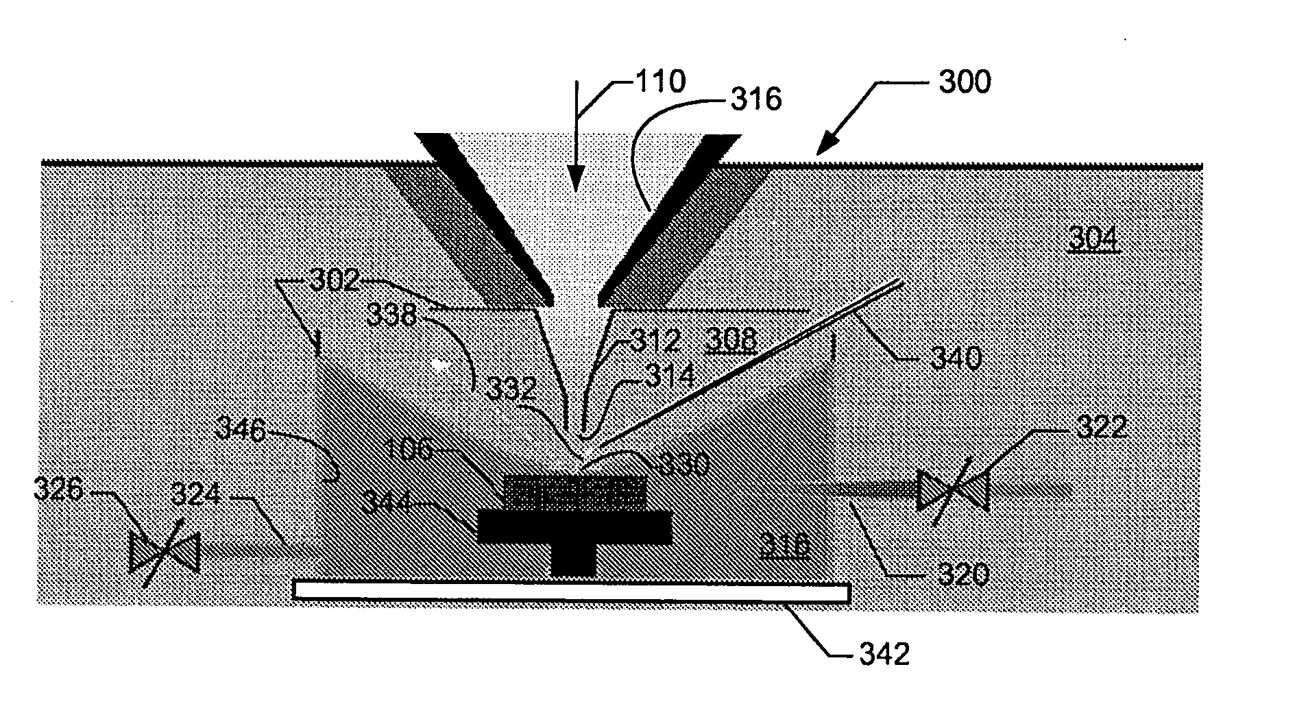
[0027]Various embodiments can solve one or more of the problems associated with HPSEM systems for imaging and beam chemistry. There are several advantages to using an HPSEM for beam chemistry. Unlike high vacuum SEM beam chemistry processing in which the processing rate is limited by the rate at which the relatively low flux of precursor molecules arrives at the substrate, processing in an HSPEM at high electron fluxes is not so limited. Moreover, an HPSEM provides for charge neutralization during processing. With some process gases, the effect on the sample can be changed from etching to deposition by changing the primary beam current density. Moreover, the pressure at the sample can be measured unambiguously by measuring the cell background pressure.

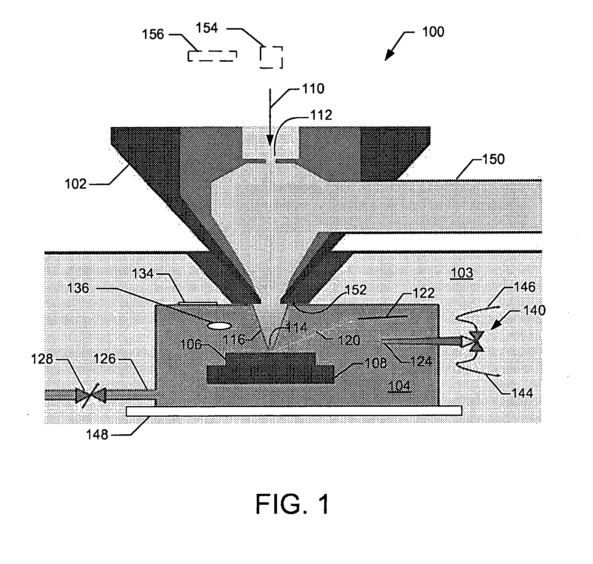
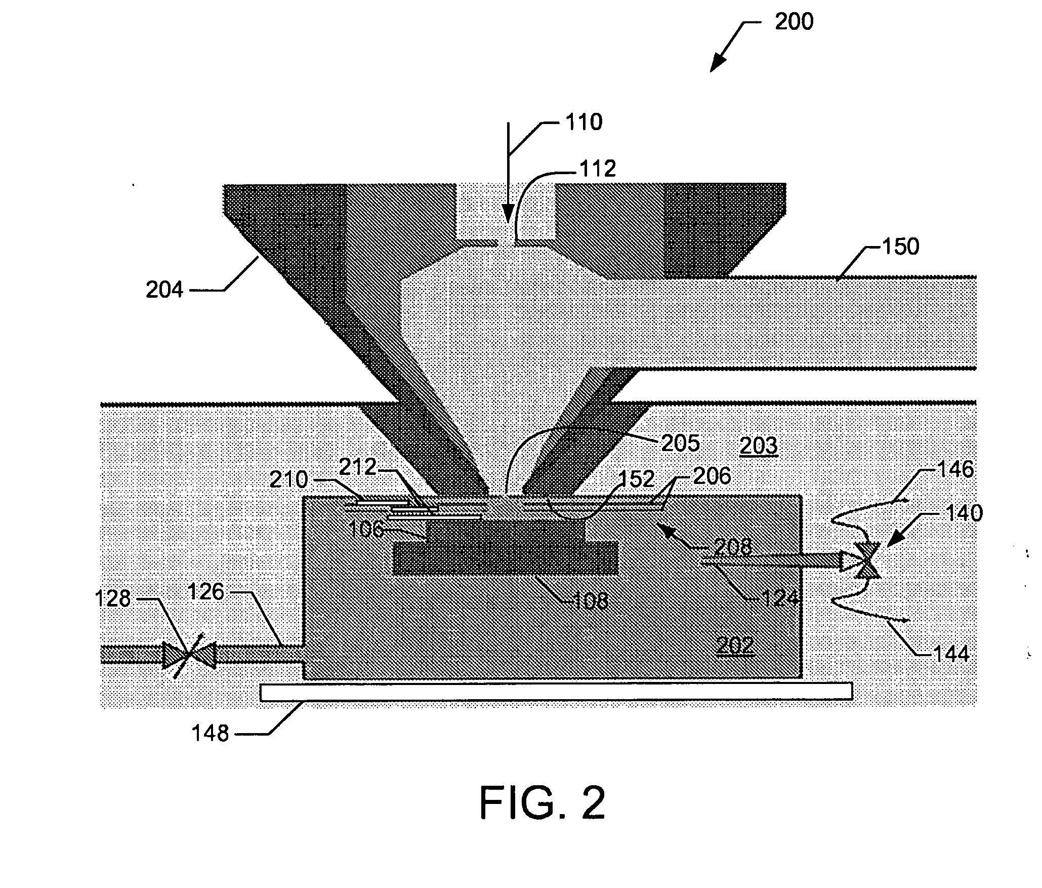
[0028]Embodiments of the invention use a cell in which a sample is positioned for charged particle beam processing. The cell is typically positioned in a sample chamber of charged particle beam system, although the sample chamber itsel...


PUM

PropertyMeasurementUnit
pressureaaaaaaaaaa
voltageaaaaaaaaaa
pressureaaaaaaaaaa

Abstract

The current invention includes methods and apparatuses for processing, that is, altering and imaging, a sample in a high pressure charged particle beam system. Embodiments of the invention include a cell in which the sample is positioned during high pressure charged particle beam processing. The cell reduces the amount of gas required for processing, thereby allowing rapid introduction, exhaustion, and switching between gases and between processing and imaging modes. Maintaining the processes gases within the cell protects the sample chamber and column from contact with the gases. In some embodiments, the temperature of the cell walls and the sample can be controlled.

Description

TECHNICAL FIELD OF THE INVENTION[0001]The present invention relates to charged particle beam systems and more particularly to electron microscopes in which the sample environment is at a relatively high pressure.BACKGROUND OF THE INVENTION[0002]In a scanning electron microscope (“SEM”), a primary beam of electrons is scanned onto a region of a sample that is to be investigated. The energy released in the impact of the electrons with the sample causes the liberation of other charged particles in the sample. The quantity and energy of these secondary particles provide information on the nature, structure and composition of the sample. The term “secondary electron” as used herein includes backscattered primary electrons, as well as electrons originating from the sample. To detect secondary particles, a SEM is often provided with one or more secondary electron detectors. The term “sample” is traditionally used to indicate any work piece being processed or observed in a charged particle ...

Claims


Application Information

Patent Timeline
Patent Type & Authority Applications(United States)
IPC IPC(8): G01N23/00
CPCH01J37/301H01J2237/31732H01J37/3056H01J2237/006H01J2237/2605H01J2237/3174H01J2237/2003H01J2237/188
Inventor KNOWLES, WILLIAM RALPHKNOWLES, RAETOTH, MILOS
Owner FEI CO
Why Eureka
Try Eureka