Phased array ultrasonic contact transducer, with a flexible wedge and a profilometer

a technology of ultrasonic contact transducer and phased array, which is applied in the direction of direction finders using ultrasonic/sonic/infrasonic waves, transmission, sound producing devices, etc., can solve the problems of difficult implementation of methods, high cost, and high cost of ultrasonic/sonic/infrasonic waves,

Inactive Publication Date: 2011-02-10
COMMISSARIAT A LENERGIE ATOMIQUE ET AUX ENERGIES ALTERNATIVES
View PDF4 Cites 13 Cited by
  • Summary
  • Abstract
  • Description
  • Claims
  • Application Information

AI Technical Summary

Problems solved by technology

However, the performance of these techniques, which use one or multiple standard elements, is quickly limited when complex geometries or surfaces are monitored.
One known solution consists of processing the signals, when they are transmitted or received, using very complex mathematical algorithms.
These methods are therefore difficult to implement and are fairly quickly limited because the signals are greatly disrupted by the complex interface between a transducer and an object to be monitored or by the need to precisely know the parameters of the acquisition, such as the geometric parameters.
The first solution can be very difficult to implement, or even impossible to use, since it requires locally sealing a feed line.
The second solution, although it optimizes the acoustic coupling, does not offset the aberrations undergone by the ultrasonic beam passing through the interface between the wedge and the piece to be monitored.
However, a transducer of this type is put directly in contact with a piece to be monitored, which leads to the existence of a dead zone of several millimeters under the surface of the piece, in which zone no monitoring can be done.
To resolve this problem, it is known to connect a delay line to each element of the “SFT” or “conformable” transducer, but this is done to the detriment of that transducer's flexibility.
Lastly, the technological limits for realizing elements reduce the directivity of such transducers and do not make it possible to perform monitoring with large incline angles of the ultrasonic beam.

Method used


Image

  • Phased array ultrasonic contact transducer, with a flexible wedge and a profilometer
  • Phased array ultrasonic contact transducer, with a flexible wedge and a profilometer
  • Phased array ultrasonic contact transducer, with a flexible wedge and a profilometer

Examples


Embodiment Construction

[0022]The present invention aims to resolve the aforementioned drawbacks.

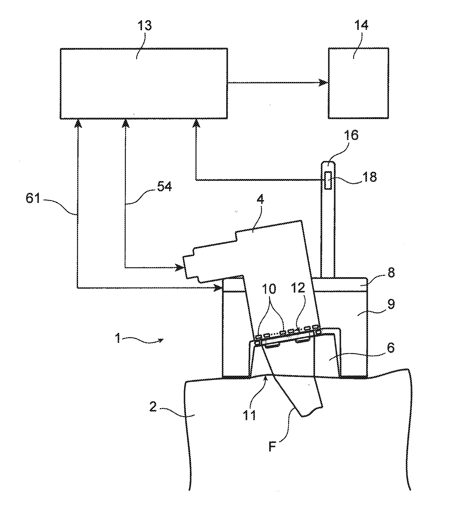
[0023]In the invention, a standard rigid phased array transducer is provided with a wedge whereof at least the front face is flexible. The acoustic coupling between the set of elements and an object to be monitored is ensured by the wedge, the deformable front face of which is capable of fitting the shape of a complex surface.

[0024]Moreover, according to another feature of the invention, real-time information on the local deformation of said front face is used to offset the delay laws during focusing of the ultrasound waves.

[0025]Of course, techniques exist that use a phased array transducer, mounted on a flexible wedge without instrumentation, and in which the surface of the object to be monitored is known a priori. Parameters such as the delay laws are then applied as a function of the position of the transducer.

[0026]These techniques are interesting in the case of a slightly irregular surface, but their inte...


PUM

PropertyMeasurementUnit
bearing forceaaaaaaaaaa
angleaaaaaaaaaa
flexibleaaaaaaaaaa

Abstract

Phased array ultrasonic contact transducer, with a flexible wedge and a profilometer. This transducer applies to the non-destructive monitoring of an object and comprises: a set of elements that are rigidly integral with each other, at least part of the elements serving as ultrasound transmitters, a wedge whereof at least the front face is flexible to be applied against the surface of the object and the rear face of which is made integral with the set of elements, and a profilometer to measure surface variations and supply signals representative thereof to allow the transmitters to create a focused ultrasonic beam whereof the characteristics are controlled in relation to the object.

Description

CROSS REFERENCE TO RELATED APPLICATIONS OR PRIORITY CLAIM[0001]This application is a national phase of International Application No. PCT / EP2009 / 054738, entitled “PHASED ARRAY ULTRASONIC CONTACT TRANSDUCER, WITH A FLEXIBLE WEDGE AND A PROFILOMETER”, which was filed on Apr. 21, 2009, and which claims priority of French Patent Application No. 08 52725 filed Apr. 23, 2008.DESCRIPTION[0002]1. Technical Field[0003]The present invention concerns a phased array ultrasonic contact transducer.[0004]This transducer can be used in the industrial field to perform non-destructive monitoring, in the medical field, and in any field requiring that the transducer be in contact with the surface of an object to be monitored and that it be flexible enough to fit the shape of that surface (the words “deformable,”“soft,” and “flexible” being synonymous in this description).[0005]Examples of applications include, in the industrial field, monitoring welding seams, elbows, and tappings, and in the medical fi...

Claims


Application Information

Patent Timeline
Patent Type & Authority Applications(United States)
IPC IPC(8): G01N29/26G10K11/34
CPCG01N29/041G01N29/225G01N29/28G01N29/262G01N29/2456
Inventor CASULA, OLIVIER
Owner COMMISSARIAT A LENERGIE ATOMIQUE ET AUX ENERGIES ALTERNATIVES
Why Eureka
Try Eureka