Method and apparatus to produce synthetic gas

Active Publication Date: 2011-02-17
AIR PROD & CHEM INC
View PDF22 Cites 45 Cited by
  • Summary
  • Abstract
  • Description
  • Claims
  • Application Information

AI Technical Summary

Problems solved by technology

Moreover, gasification system components, for example, a gasification reactor refractory, may limit a temperature of reaction, and therefore limit an oxygen-to-carbon ratio, thereby limiting the use of carbon in forming CO and CO2 as well as the as

Method used


Image

  • Method and apparatus to produce synthetic gas
  • Method and apparatus to produce synthetic gas
  • Method and apparatus to produce synthetic gas

Examples


Embodiment Construction

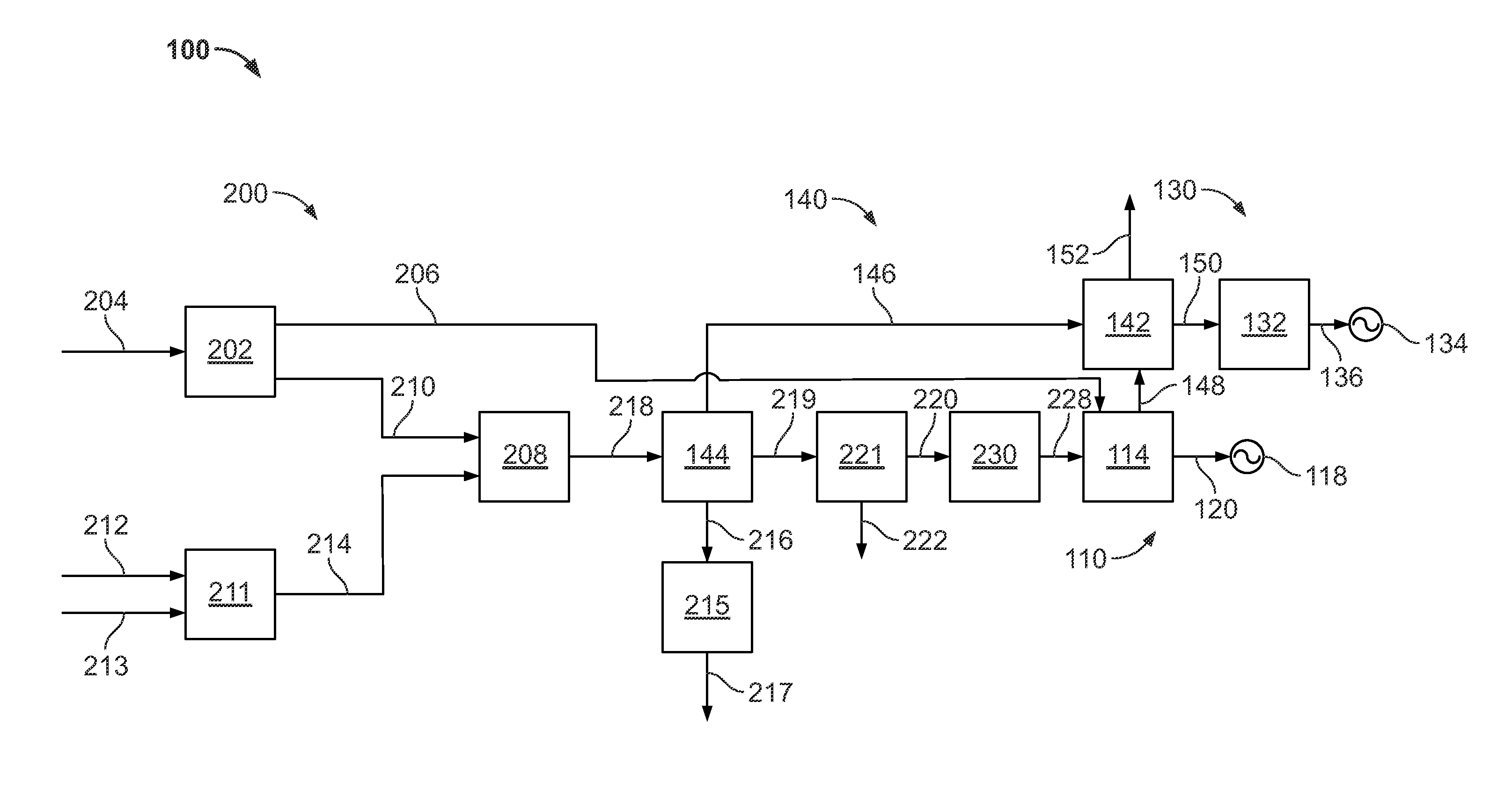
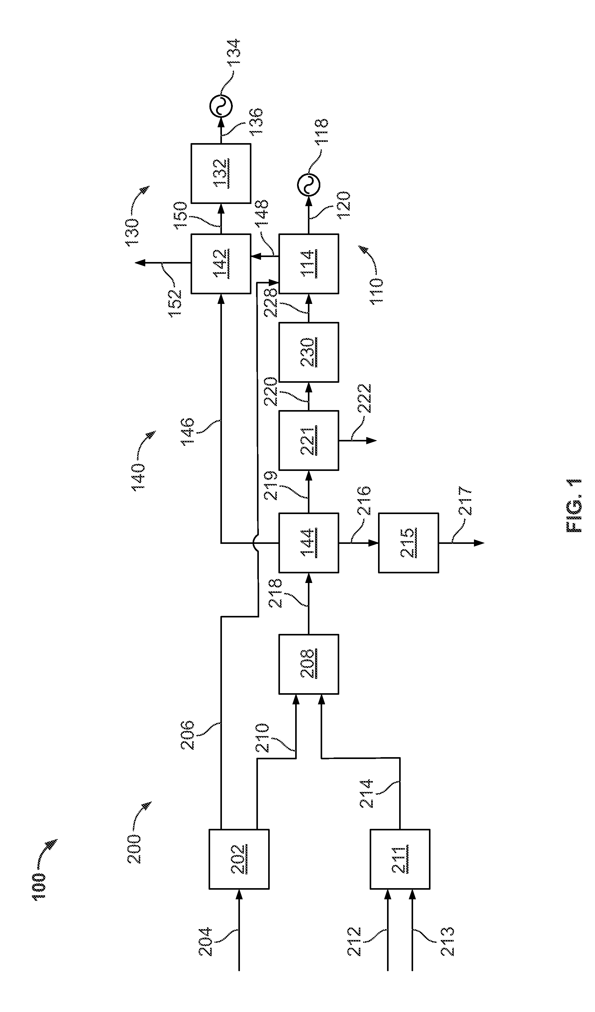
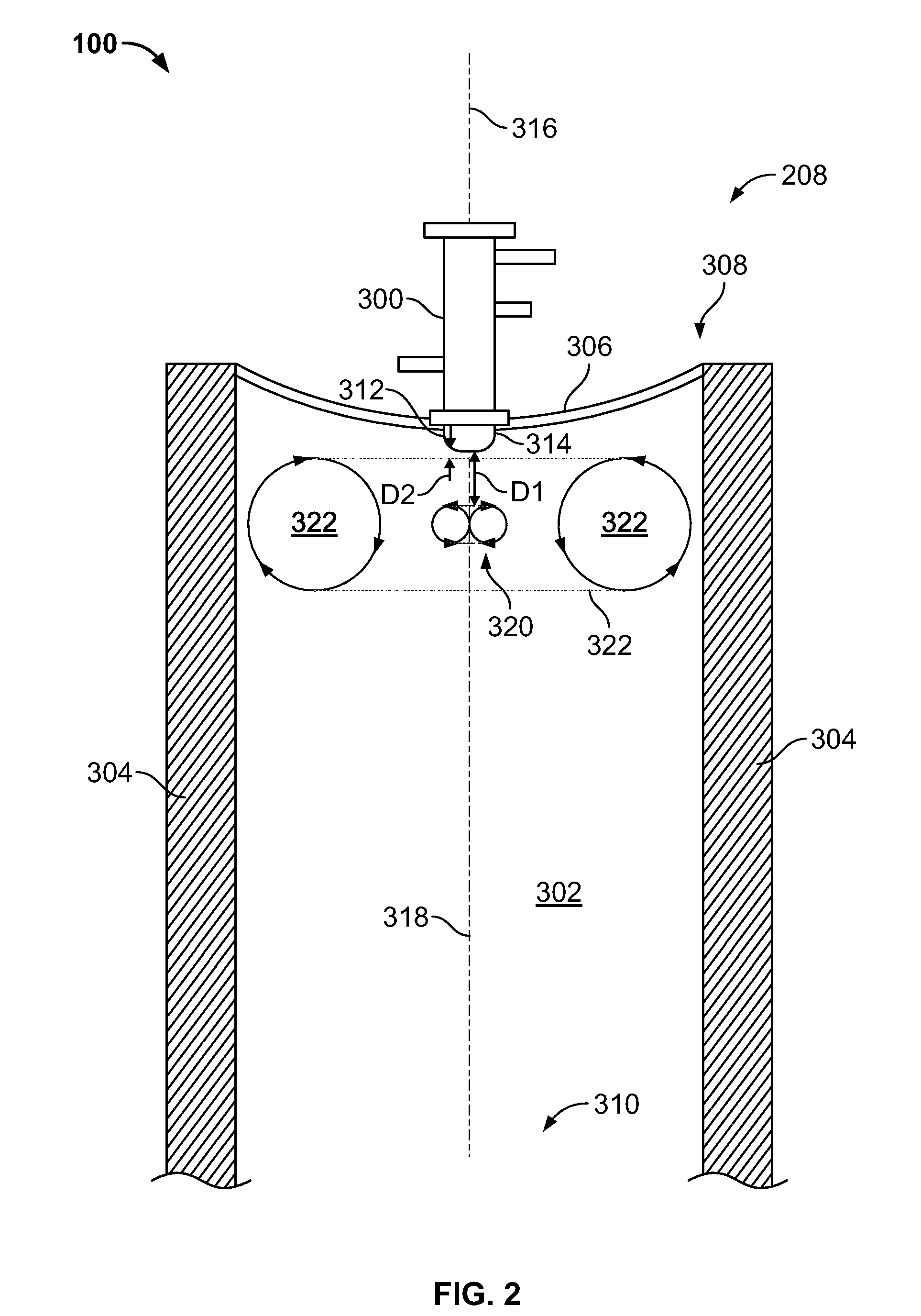
[0032]The method and apparatus for synthetic gas, or syngas, production as described herein facilitates operation of a gasification system, such as a gasification system integrated with a combined-cycle power generation plant, integrated gasification combined-cycle (IGCC) power generation plants, specifically, syngas production systems, and more specifically, gasification reactors. Specifically, injecting syngas production fluid streams into the gasification reactor at predetermined orientations increases syngas production efficiency. More specifically, forming substantially annular sheets of the reactant streams and intersecting them as described herein facilitates forming recirculation zones. Moreover, forming the recirculation zones facilitates increasing an effective residence time and / or residence time distribution of the reactants in relation to each other such that a greater efficiency and effectiveness of chemical reactions between the reactants occurs. Furthermore, configur...


PUM


Abstract

A method of producing a synthetic gas (syngas) includes injecting a plurality of reactant streams into a gasification reactor via at least one injection device having a plurality of injection annuli, an inner portion that extends annularly about a centerline extending through the at least one injection device, and an outer portion extending substantially annularly about the inner portion. At least a portion of the outer portion is oriented obliquely with respect to the at least one injection device centerline. The method also includes mixing at least a portion of each of the streams together such that a plurality of recirculation zones is defined by the streams. The method further includes producing a syngas within the recirculation zones via mixing at least a portion of each of the streams. The injection device includes an inner portion that extends annularly about a centerline extending through the injection device. The device also includes an outer portion extending substantially annularly about the inner portion that includes at least one of at least one carbonaceous reactant injection port oriented obliquely with respect to the injection device centerline and at least one outer face oriented obliquely with respect to the injection device centerline.

Description

BACKGROUND OF THE INVENTION[0001]The present invention relates generally to gasification systems, such as gasification systems used in an integrated gasification combined-cycle (IGCC) power generation plants, and more particularly, to methods and apparatus for optimizing synthetic gas production with a gasification system injection device.[0002]Most known IGCC plants include a gasification system that is integrated with at least one power-producing turbine system. For example, known gasification systems convert a mixture of fuel, air or oxygen, liquid water, and / or steam, and / or CO2 into a synthetic gas, or “syngas”. The syngas is channeled to the combustor of a gas turbine engine, which powers a generator that supplies electrical power to a power grid. Exhaust from at least some known gas turbine engines is supplied to a heat recovery steam generator (HRSG) that generates steam for driving a steam turbine. Power generated by the steam turbine also drives an electrical generator tha...

Claims


Application Information

Patent Timeline
IPC IPC(8): C10J3/68C10J3/00F16K49/00C10J1/207
CPCF23D1/005Y02E20/18C10J3/506Y02E20/16C10J2300/0959C10J2300/0973C10J2200/152C10J2300/093Y10T137/6416
Inventor SPROUSE, KENNETH M.FARHANGI, SHAHRAMSAXELBY, ROBERT M.
Owner AIR PROD & CHEM INC
Why Eureka
Try Eureka