Optical techniques for the measurement of chest compression depth and other parameters during cpr

a chest compression and optical sensor technology, applied in the field of chest compression depth measurement, can solve the problems of confusion and hindering the individual in delivering proper treatment, poor quality of cpr, and insufficient memory retention of proper cpr technique and protocol, etc., to achieve accurate measurement of chest rise, accurate gauge compression depth, and high accuracy

Active Publication Date: 2011-02-17
STRYKER CANADA ULC
View PDF13 Cites 116 Cited by
  • Summary
  • Abstract
  • Description
  • Claims
  • Application Information

AI Technical Summary

Benefits of technology

[0024]The use of optical compression depth techniques also has applications in CPR training. The device may be used to accurately gauge compression depth while training individuals in CPR. This technique is highly accurate and can be used to properly train individuals to administer CPR at the proper depth, a common problem plaguing many rescuers.
[0025]Furthermore, optical compression depth techniques have further advantages. Unlike the use of gyroscope or accelerometer based sensors, optical techniques do not suffer from cumulative error and do not rely on inertial measurements that can be affected by the surrounding environment. When using accelerometers, the victim and rescuer must not experience any external movement such as that caused by transport of the victim in an ambulance or helicopter. Such random and non-isolated movements of the patient will invalidate any measurements taken by inertial sensors. Furthermore, optical sensor techniques have the advantage of being useful in a wide-array of CPR related measurements not limited to compression depth. The optical sensors can be used to visualize the size of a patient and immediately gauge the body type and instruct the user accordingly. For instance, there is a significant difference between infant and adult CPR and automatic body type compensation algorithms are highly beneficial in a fast-moving emergency where every second matters. Furthermore, optical measurement techniques can be used to accurately measure chest rise during artificial respiration and ensure that proper ventilation is being administered in between compressions. In addition, optical measurements of the chest of the victim and the hands of the rescuer can help ensure that the rescuer has positioned his or her hands in the anatomically correct location for effective CPR.
[0026]Optical compression depth measurement techniques are a highly accurate and likely inexpensive method of determining compression depth during the administration of CPR. Optical methods do not suffer from the drawbacks of accelerometer-based techniques. They are inherently more accurate as they do not experience cumulative errors or inaccuracies due to movement of the victim or rescuer.

Problems solved by technology

However, the quality of CPR is often poor.
Memory retention of proper CPR technique and protocol may be inadequate in most individuals and the anxiety of an emergency situation may confuse and hinder an individual in delivering proper treatment.
According to the journal of the American Medical Association (2005), cardiopulmonary resuscitation (CPR) is often performed inconsistently and inefficiently, resulting in preventable deaths.
Mere months after the completion of standard CPR training and testing, an individual's competency at performing effective chest compressions often deteriorates significantly.
In addition to too shallow compressions, too forceful compressions may also be problematic.
Such consequences may be due to excessive force or compression depth.
Once again, lack of practice may be responsible for these injuries.
However, these devices are often expensive and inaccessible to the lay individual who does not have a defibrillator on hand or cannot operate such a device.
Furthermore, such devices are often not portable nor are they easily accessible.
Simple devices with illuminated bar graph or LED displays indicating compression force are often cumbersome in design and non-intuitive in use.
Such a device may be uncomfortable to the patient and user and often has minimal data output.
Thus, misuse of such a device is most likely rendering it a hindrance rather than an aid.
Such a device is cumbersome and heavy to transport, requires time to set up and activate and is expensive.
However, this technology requires defibrillator pads to be placed across the chest of the victim and is, consequently, relatively time consuming to activate.
The commercially available device, Q-CPR by Phillips Medical, must be attached to an expensive hospital-grade defibrillator making it expensive, heavy and inaccessible to the lay user.
Any acceleration data from accelerometers used to measure the depth of chest compression during CPR is prone to cumulative errors.
Consequently, these sensors are not suitable for highly accurate or detailed data collection regarding CPR parameters and can only be relied on for approximate depth values.
Furthermore, the use of an accelerometer in a CPR monitoring device without an external reference is prone to error if the patient or rescuer is mobile.
For example, if the patient is being medically transported in an ambulance, helicopter or on a gurney, the accelerometer is unable to differentiate between the external movement of the patient and the compressions of the chest.
In any type of non-stationary environment, an accelerometer based device is unreliable and ineffective.
The use of an accelerometer to calculate compression depth also relies on complicated and error-prone calculations to compensate for the angle and tilt of the compression device.
If the accelerometer is not perfectly level on the chest of the victim and its movement is not perfectly vertical, errors will accumulate and must be accounted for by the angle of the two horizontal axes.
Due to the additional circuitry and sensory within them, these defibrillator pads are substantially more expensive and must be disposed of after each use.
Therefore, relatively expensive sensory must be routinely discarded due to the design of the product.
This technique relies on the observational skills of the instructor and thus may be prone to human error.
Furthermore, for effective training to take place, each student must be observed separately thereby occupying a significant amount of time and decreasing the number of students who can be trained at one time.
Such random and non-isolated movements of the patient will invalidate any measurements taken by inertial sensors.

Method used


Image

  • Optical techniques for the measurement of chest compression depth and other parameters during cpr
  • Optical techniques for the measurement of chest compression depth and other parameters during cpr
  • Optical techniques for the measurement of chest compression depth and other parameters during cpr

Examples


Embodiment Construction

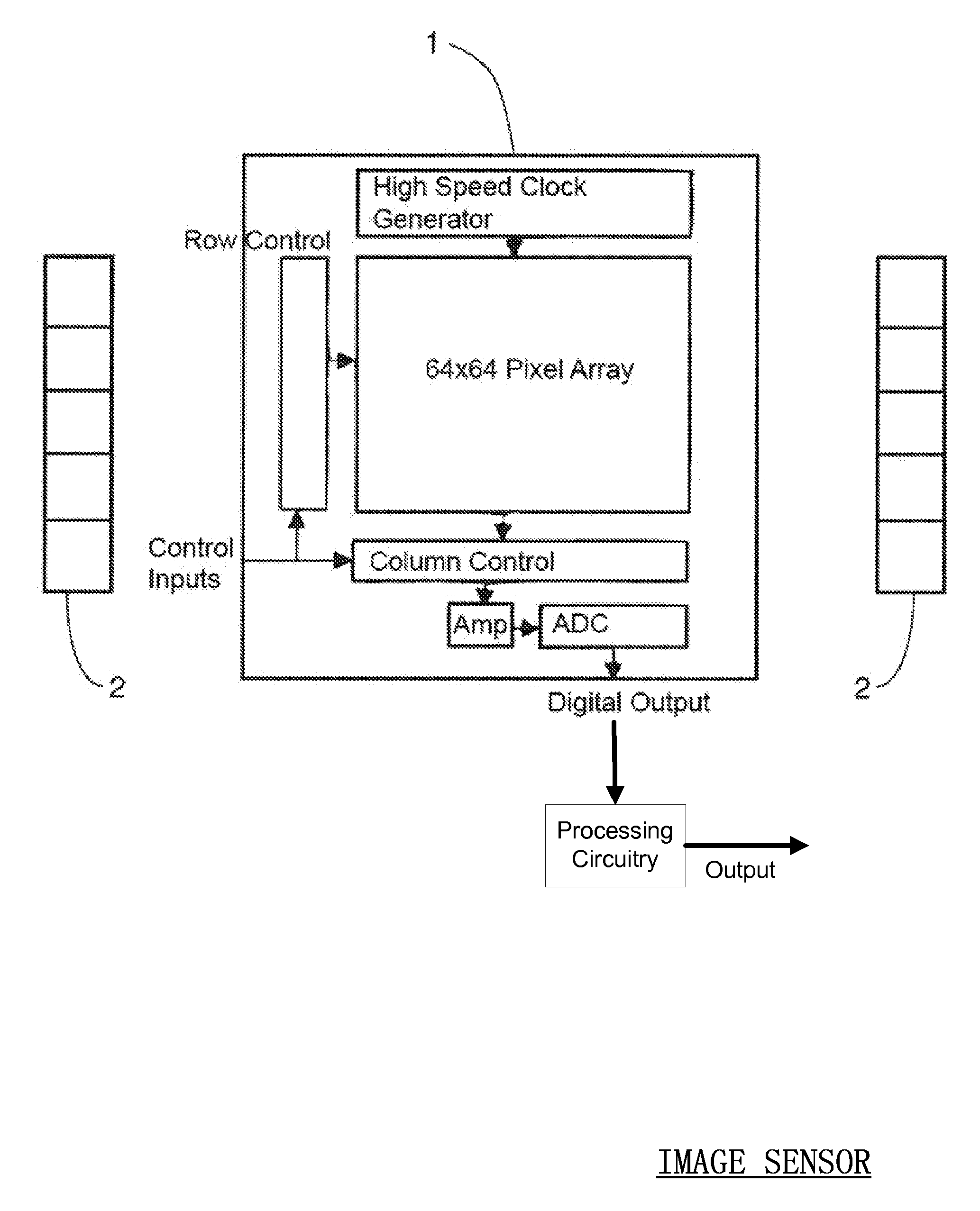
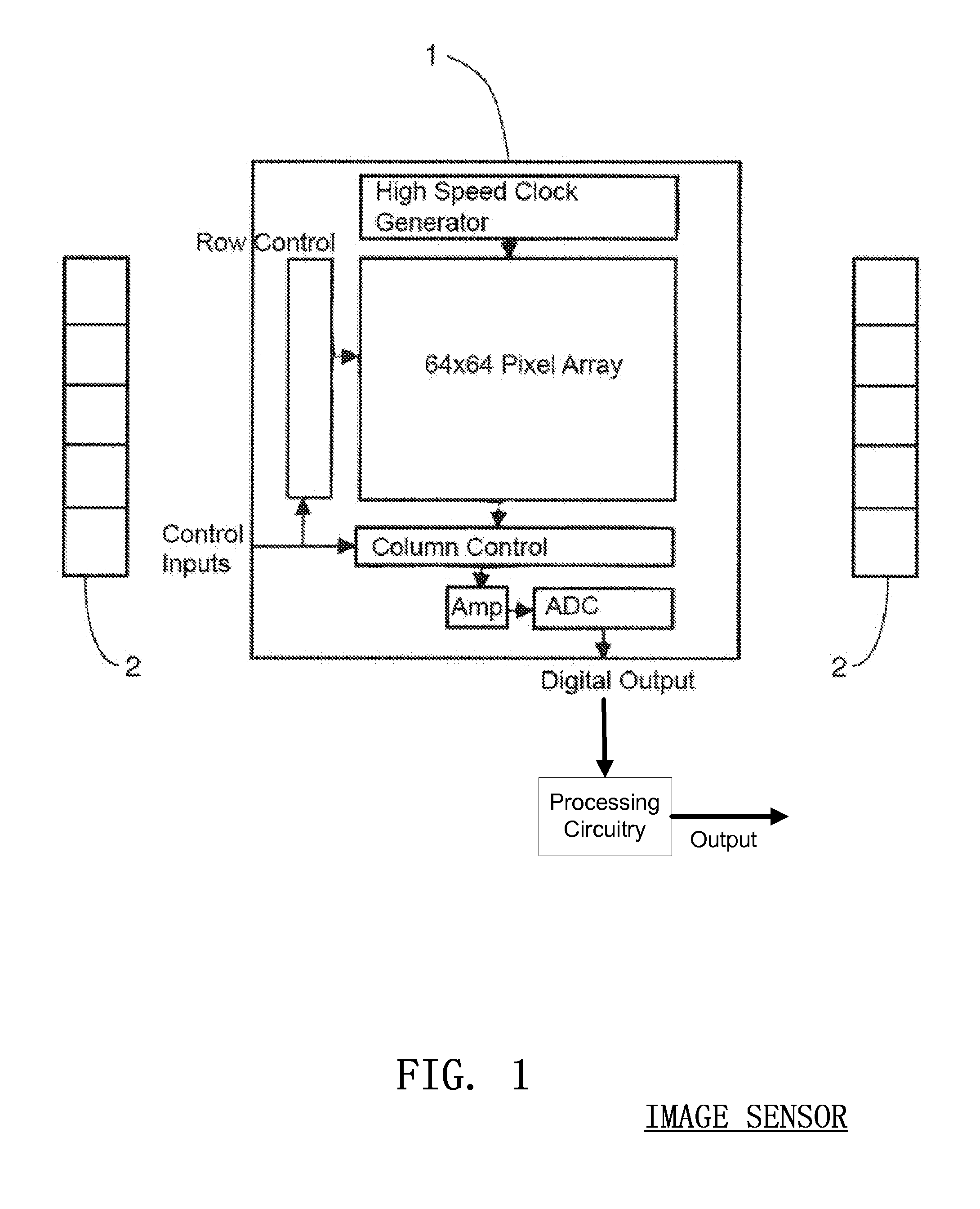
[0046]An image sensor is a device that converts an optical image to an electric signal. The two most widely recognized types of image sensors are the (Complementary Metal Oxide Semiconductor) CMOS and CCD (Charge Coupled Device) sensors. A CMOS chip is a type of active pixel sensor made using the CMOS semiconductor process. Extra circuitry next to each pixel sensor converts the light energy to a voltage. Additional circuitry on the chip converts the voltage to digital data. A CCD is an analog device. When light strikes the chip it is held as a small electrical charge in each pixel sensor. The charges are converted to voltage one pixel at a time as they are read from the chip. Additional circuitry in the camera converts the voltage into digital information.

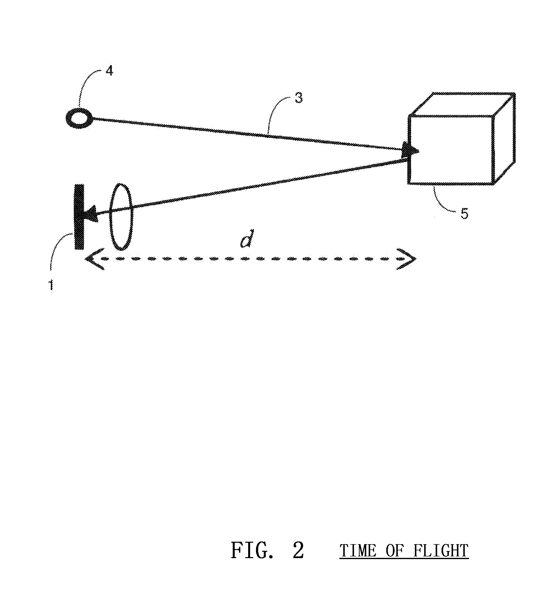
[0047]A CMOS image sensor 1 is illustrated in FIG. 1 Along with an infrared illumination source 2, the image sensor 1 determines the three-dimensional characteristics of a scene by measuring the time-of-flight of the illumination f...


PUM


Abstract

Embodiments of the present invention are related to a method and device for the determination and calculation of the depth of chest compressions during the administration of cardiopulmonary resuscitation (CPR). Embodiments use an optical sensor to monitor the distance that a victim's chest is displaced during each compression throughout the administration of CPR. The optical sensor is most commonly an image sensor such as a CMOS or CCD sensor, and more specifically a CMOS image sensor capable of three-dimensional imaging based on the time-of-flight principle. An infrared emitter may illuminate the victim's body and any visible piece of ground beside the victim. As the infrared light interacts with any surfaces it encounters, it is reflected and returns to the image sensor where the time of flight of the infrared light is calculated for every pixel in the image sensor. The distance data is used to gauge the effective displacement of the victim's chest. The optical sensors can be used to visualize the size of a patient and immediately gauge the body type and instruct the user accordingly. Furthermore, optical measurement techniques can be used to accurately measure chest rise during artificial respiration and ensure that proper ventilation is being administered in between compressions. In addition, optical measurements of the chest of the victim and the hands of the rescuer can be used to help ensure that the rescuer has positioned his or her hands in the anatomically correct location for effective CPR.

Description

CROSS REFERENCE TO RELATED APPLICATIONS[0001]This application is a non-provisional application of and claims benefit from U.S. Provisional application 61 / 227,637, filed Jul. 22, 2009, titled OPTICAL TECHNIQUES FOR THE MEASUREMENT OF CHEST COMPRESSION DEPTH AND OTHER PARAMETERS DURING CPR, which is hereby incorporated by reference.FIELD OF THE INVENTION[0002]This disclosure generally relates to the measurement of chest compression depth during the administration of cardiopulmonary resuscitation (CPR), specifically to compression depth measurement by use of optical sensors.BACKGROUND OF THE INVENTION[0003]There are currently an estimated 40,000 incidences of cardiac arrest every year in Canada, most of which take place outside of hospital settings. The odds of an out-of-hospital cardiac arrest currently stand at approximately 5%. In the U.S., there are about 164 600 such instances each year, or about 0.55 per 1000 population. There is a desire to decrease these out-of hospital inciden...

Claims


Application Information

Patent Timeline
Patent Type & Authority Applications(United States)
IPC IPC(8): A61H31/00
CPCA61B5/0064A61B5/113A61H31/005A61H2201/5058A61N1/046A61N1/0472G09B23/288G06T7/2066G06T7/60G06T2207/10016G06T2207/10028G06T2207/30004A61N1/3968G06T7/269A61H2201/5092A61N1/3925A61N1/3993G06T7/0012G06T7/20
Inventor CENTEN, COREY JAMES
Owner STRYKER CANADA ULC
Why Eureka
Try Eureka