Imaging device

a technology of an image and a lens, applied in the field of image imaging devices, can solve the problems of stray light, loss of information of an image which is desired to be formed, loss of normal image information, etc., and achieve the effect of reducing stray ligh

Inactive Publication Date: 2011-02-24
KONICA MINOLTA OPTO
View PDF3 Cites 46 Cited by
  • Summary
  • Abstract
  • Description
  • Claims
  • Application Information

AI Technical Summary

Benefits of technology

[0048]According to the present invention, based on a mode signal of a mode signal generation section, a mode control section causes an image generation section to operate in the normal mode or in the polarized light component reduction mode to form a normal image or a polarized light component reduced image in the image generation section. Therefore, when imaging is carried out in the situation where stray light having a polarized light component is likely generated in the imaging device, namely, when stray light is likely to occur, the imaging device is automatically switched to the polarized light component reduction mode, whereby a polarized light component reduced image, in which occurrence of stray light having a polarized light component is reduced or eliminated, is formed. In contrast, when stray light is unlikely to occur, the imaging device is automatically switched to the normal mode, whereby a normal image, which is more natural than the polarized light component reduced image, is formed. Thus, an imaging device capable of automatically switching, depending on the situation, whether to reduce stray light or not can be provided.

Problems solved by technology

When imaging is carried out using a camera, if a relatively intense light source exists in a photographed image plane or in the vicinity of the photographed image plane, when a light beam passes through an optical system, the light beam may reflect on the lens surface of the optical system, an optical flat plate, or a lens barrel without passing through a light beam passing position expected by design, resulting in occurrence of stray light.
In such a case, when this stray light reaches an imaging element, an image of the light source may be formed on a position where no image is normally formed, or information of an image which is desired to be formed may be lost.
Further, when image information is relatively important, for example, in a car-mounted camera, a monitoring camera, or a measurement camera and when this stray light reaches the imaging element, normal image information is lost, resulting in a more critical problem.
However, for example, when an image signal output from the imaging element is subjected to image processing and thereby stray light having reached the imaging element is reduced, reduction thereof may be difficult to carry out or an unnatural image may be obtained from the reduction.
Further, in cases in which stray light is always reduced, even under a situation without stray light, polarized light information is lost, whereby normal image information is also lost in an undesirable manner Namely, on one hand, by reduction of the stray light, normal image information can be obtained.
On the other hand, normal image information under a situation without stray light is lost.
However, in Patent Document 1, no disclosure is made with respect to control of whether to reduce stray light or not, depending on situations.

Method used


Image

  • Imaging device
  • Imaging device
  • Imaging device

Examples


first embodiment

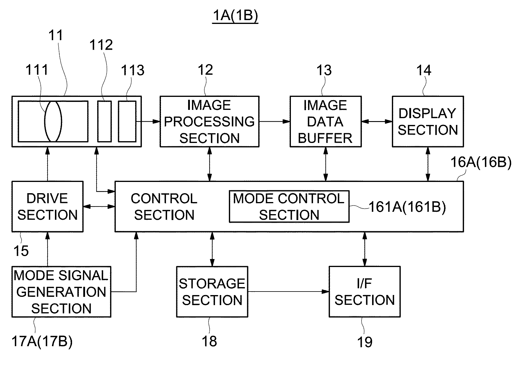
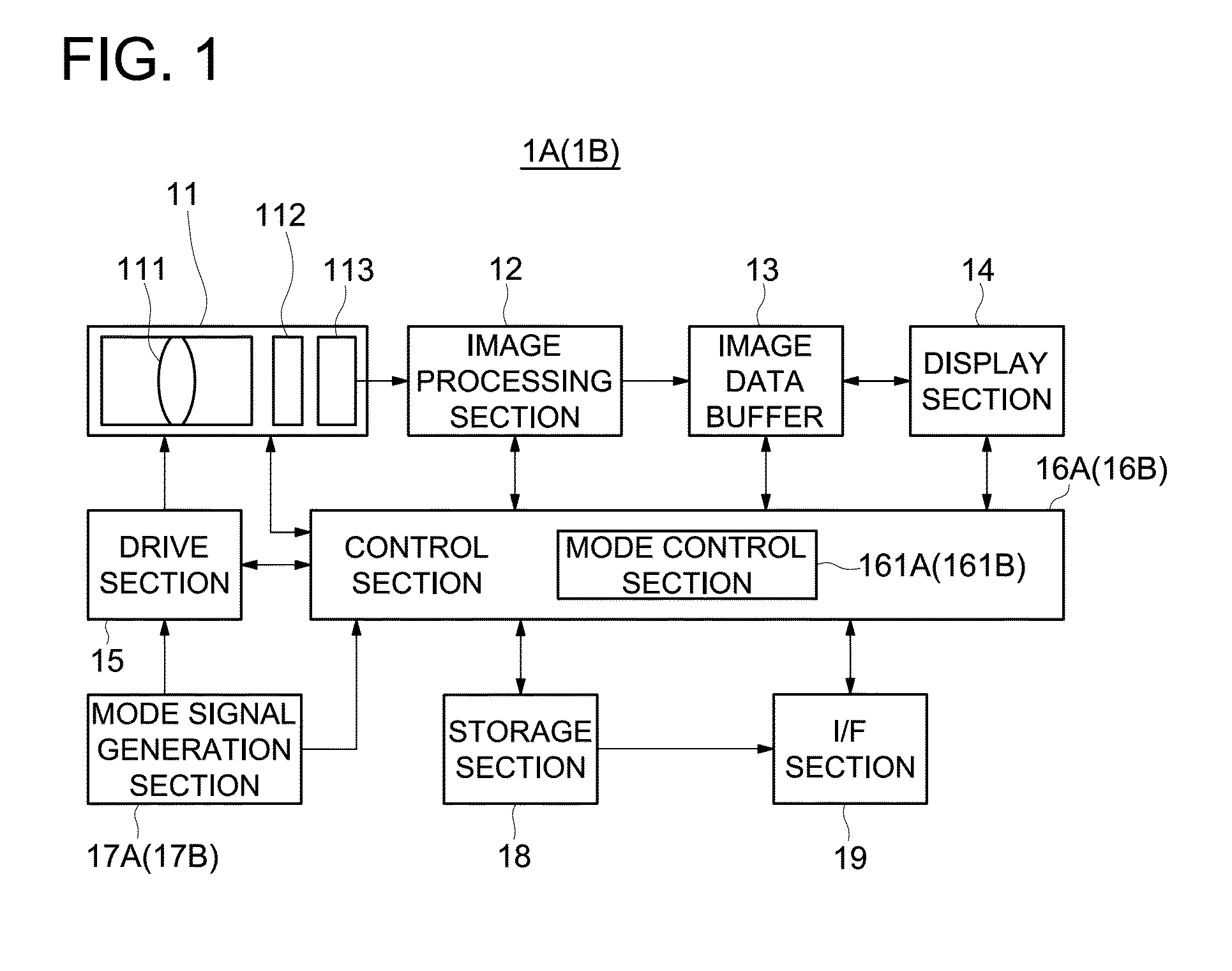
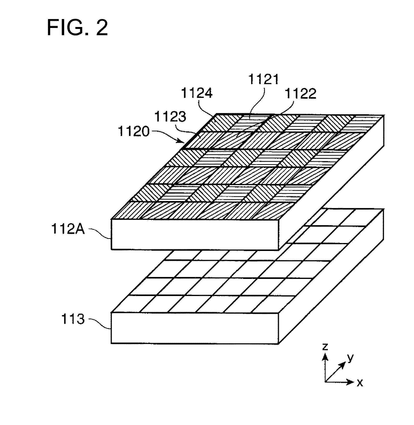
[0100]FIG. 1 is a block diagram showing a constitution of an imaging device of the embodiment. FIG. 2 is a view showing the constitution of a polarization imaging system. And, FIGS. 3A and 3B are views illustrating the intensity fm(i,j) of transmitted light received by the polarization imaging device.

[0101]In FIG. 1, an imaging device 1A is constituted by an imaging section 11, an image processing section 12, an image data buffer 13, a display section 14, a drive section 15, a control section 16A, a mode signal generation section 17A, a storage section 18, and an interface section (I / F section) 19.

[0102]The imaging device 1A includes, for example, a car-mounted camera mounted in a moving body, a surveillance camera for surveillance, and a measurement camera for measurement. Such a monitoring camera is for monitoring the surrounding environment. From the viewpoint of the ability to monitor a wider area, the viewing angle of the imaging optical system 111 is desired to be relatively l...

second embodiment

[0136]In the first embodiment, the mode signal generation section 17A was constituted by an optical sensor. In a second embodiment, a mode signal generation section 17B is constituted by a clock section to tell time. Therefore, the imaging device 1B of the second embodiment is the same as the imaging device 1A of the first embodiment except that a mode signal generation section 17B and the mode control section 161B of a control section 16B are provided, instead of the mode signal generation section 17A and the mode control section 161A of the control section 16A in the imaging device 1A of the first embodiment, respectively. Therefore, description is omitted except for the difference.

[0137]The mode signal generation section 17B constituted by a clock section outputs a current time to the control section 16B as a mode signal in response to a control signal output from the control section 16B. Herein, the mode signal generation section 17B of the clock section may functionally be cons...

third embodiment

[0142]FIG. 4 is a block diagram showing the constitution of an imaging device in a third embodiment. In the first embodiment, the mode signal generation section 17A was constituted by an optical sensor. However, in the third embodiment, the imaging element 113 of an imaging section 11 is also used as a mode signal generation section. Thus, as shown in FIG. 4, the imaging device 1C of the third embodiment is constituted by an imaging section 11 functioning also as the mode signal generation section, an image processing section 12, an image data buffer 13, a display section 14, a drive section 15, a control section 16C, a storage section 18, and an If section 19. A separate constituent member, as shown in the imaging devices 1A and 1B of the first and second embodiments, functioning as the mode signal generation section is not provided. The imaging section 11, the image processing section 12, the image data buffer 13, the display section 14, the drive section 15, the storage section 1...


PUM


Abstract

A mode control section controls an image generation section to operate in a normal mode or a polarized light component reduction mode on the basis of a mode signal from a mode signal generation section to cause the image generation section to form a normal image or a polarized light component reduced image. When the possibility of occurrence of stray light is high, the imaging device automatically switches to the polarized light component reduction mode and when the possibility of occurrence of the stray light is low, the imaging device automatically switches to the normal mode. The polarized light component reduced image is obtained by reducing or eliminating stray light having a polarized light component, and the normal image is formed without reducing the stray light. Thus, the imaging device is capable of automatically switching between the two modes.

Description

RELATED APPLICATIONS[0001]This application is a U.S. National Phase Application under 35 U.S.C. 371 of International Application No. PCT / JP2009 / 055052, filed. Mar. 16, 2009, which claims priority to Japanese Patent Application No. 2008-081538, filed Mar. 26, 2008.TECHNICAL FIELD[0002]The present invention relates to an imaging device capable of generating a normal image and a polarized light component reduced image in which a specific polarized light component is eliminated or reduced.BACKGROUND ART[0003]Over recent years, cameras have been mounted in various apparatuses such as vehicles or robots.[0004]When imaging is carried out using a camera, if a relatively intense light source exists in a photographed image plane or in the vicinity of the photographed image plane, when a light beam passes through an optical system, the light beam may reflect on the lens surface of the optical system, an optical flat plate, or a lens barrel without passing through a light beam passing position ...

Claims


Application Information

Patent Timeline
Patent Type & Authority Applications(United States)
IPC IPC(8): H04N7/18H04N5/225
CPCB60R2300/10B60R2300/804B60R2300/8053B60R2300/8066H04N5/2254G02B27/281G03B15/00H04N5/217G02B27/0018H04N23/81H04N23/60
Inventor FUKUTA, YASUNARIFUKUSHIMA, AKIRATERAMOTO, MIYUKIMATSUSAKA, KEIJI
Owner KONICA MINOLTA OPTO
Why Eureka
Try Eureka