
Quasi-optical LED package structure for increasing color render index and brightness

Active Publication Date: 2011-03-03
PARAGON SEMICON LIGHTING TECH
View PDF4 Cites 71 Cited by
  • Summary
  • Abstract
  • Description
  • Claims
  • Application Information

AI Technical Summary

Benefits of technology

[0007]Moreover, the present invention can form an annular resin frame (such as an annular white resin frame) with any shapes by coating method. In addition, the position of a translucent package resin body such as phosphor resin can be limited in the resin position limiting space by using the annular resin frame, and the shape of the translucent package resin body can be adjusted by using the annular resin frame. Therefore, the present invention can apply to increase light-emitting efficiency of LED chips and control light-projecting angle of LED chips.
[0012]Furthermore, the translucent package resin body is limited in the resin position limiting space by using the annular resin frame in order to control the usage quantity of the translucent package resin body. In addition, the surface shape and the height of the translucent package resin body can be adjusted by control the usage quantity of the translucent package resin body in order to adjust light-projecting angles of the white light beams. Moreover, the blue light beams generated by the LED chips can be reflected by an inner wall of the annular resin frame in order to increase the light-emitting efficiency of the LED package structure of the present invention.

Problems solved by technology

These lamps commonly have the disadvantages of quick attenuation, high power consumption, high heat generation, short working life, high fragility, and being not recyclable.
Further, the rapid flow of electrons (about 120 per second) through the electrodes of a regular fluorescent bulb causes an unstable current at the onset of lighting a fluorescent bulb, resulting in a flash of light that is harmful to the sight of the eyes.
However, the high frequency electronic ballast is not detachable when installed in a fluorescent or power-saving bulb, the whole lamp assembly becomes useless if the bulb is damaged.
Furthermore, because a fluorescent bulb contains a mercury coating, it may cause pollution to the environment when thrown away after damage.

Method used


Image

  • Quasi-optical LED package structure for increasing color render index and brightness
  • Quasi-optical LED package structure for increasing color render index and brightness
  • Quasi-optical LED package structure for increasing color render index and brightness

Examples


first embodiment

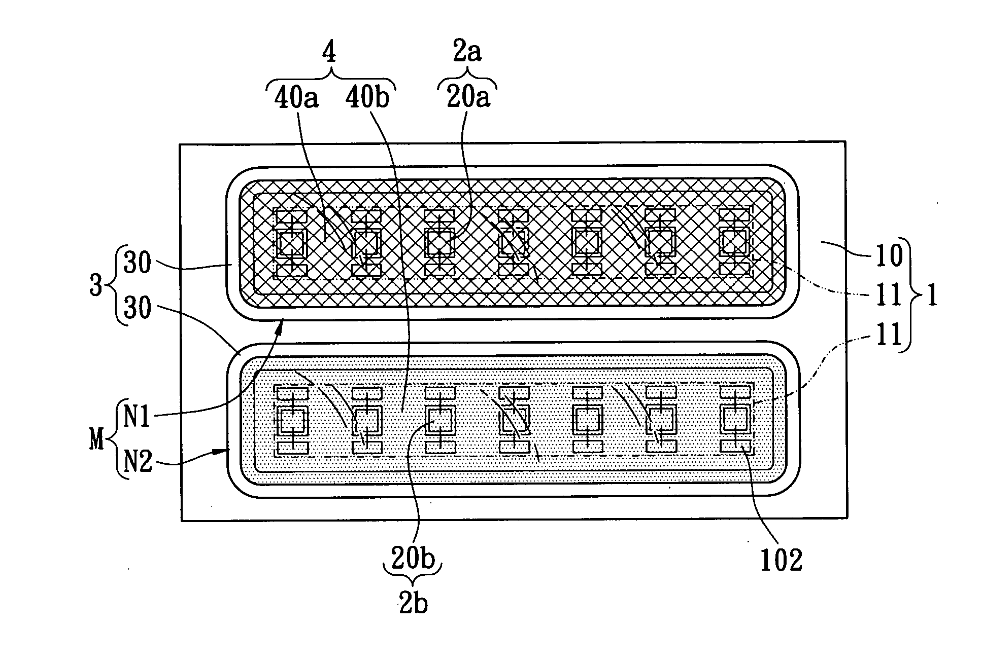
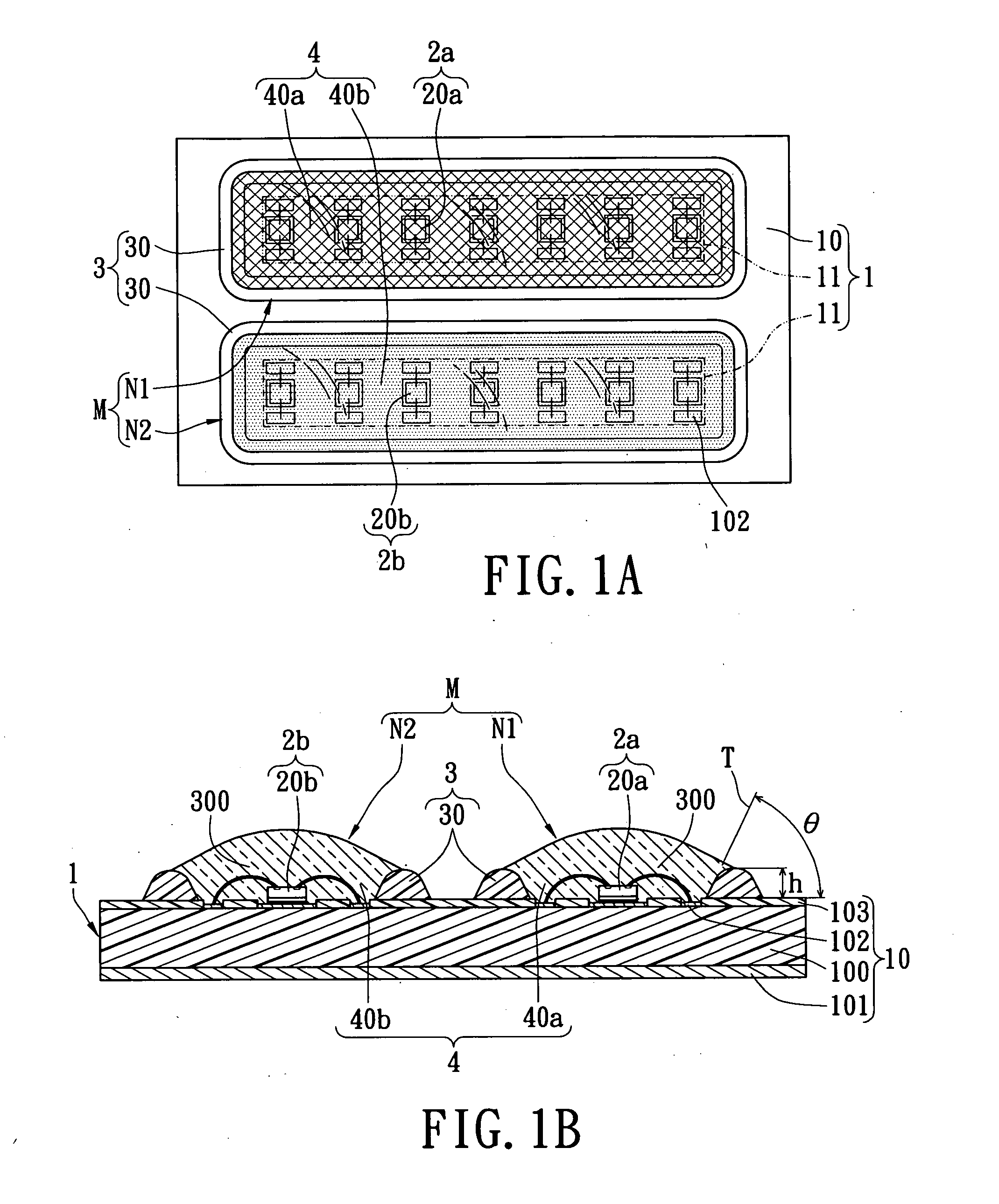
[0036]Referring to FIGS. 1A and 1B, the present invention provides a quasi-optical LED package structure M for increasing color render index and brightness, including: a substrate unit 1, a light-emitting unit, a frame unit 3 and a package unit 4.

[0037]The substrate unit 1 has at least one substrate body 10 and at least two chip-placing areas 11 formed on the at least one substrate body 10. In addition, the substrate body 10 has a circuit substrate 100, a heat-dissipating layer 101 disposed on a bottom surface of the circuit substrate 100, a plurality conductive pads 102 disposed on a top surface of the circuit substrate 100, and an insulative layer 103 disposed on the top surface of the circuit substrate 100 in order to expose the conductive pads 102. Hence, the heat-dissipating efficiency of the circuit substrate 100 is increased by using the heat-dissipating layer 101, and the insulative layer 103 is a solder mask for exposing the conductive pads 102 only in order to achieve loca...

second embodiment

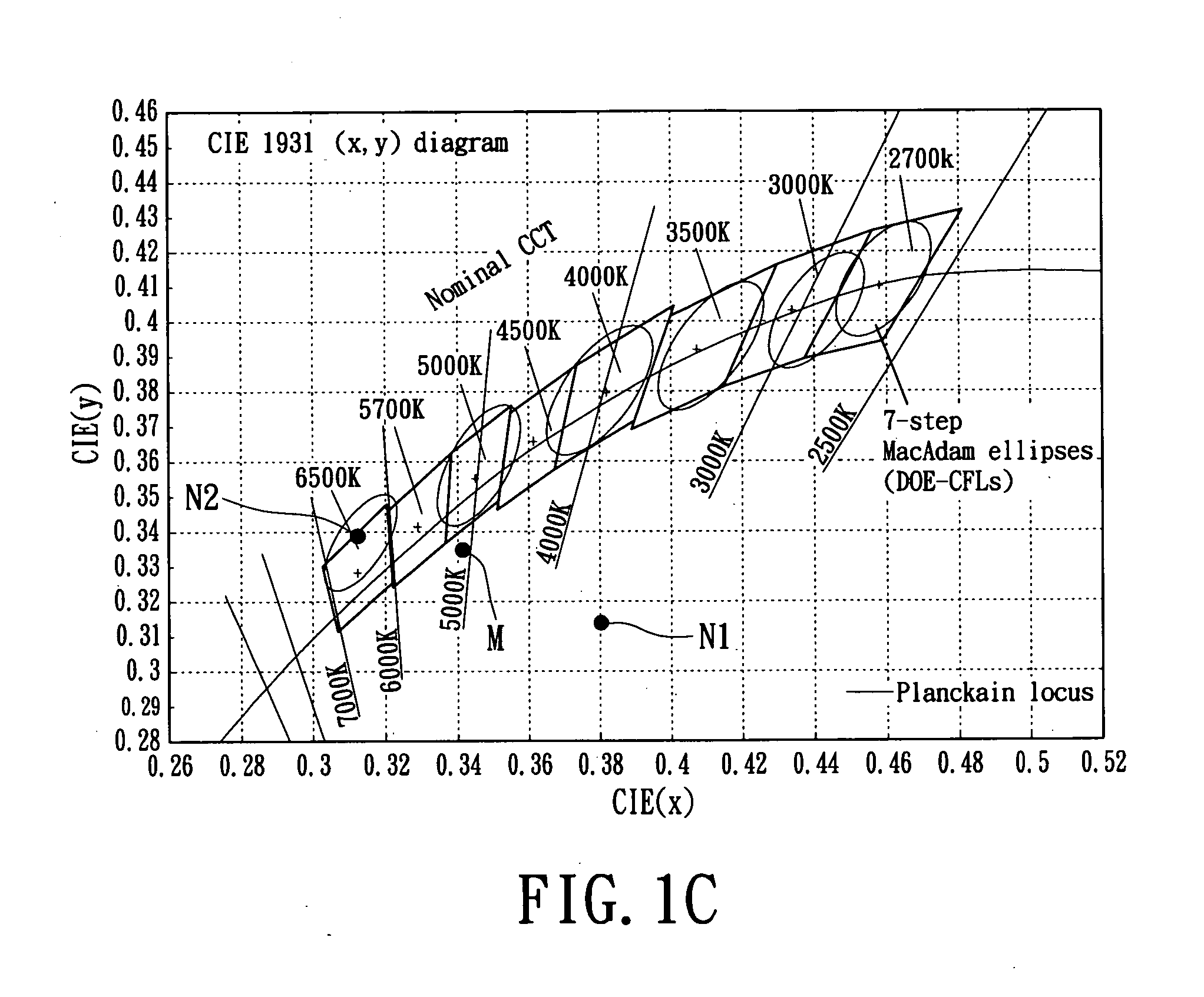
[0052]The second embodiment provides four sets of electric current for the first light-emitting structures N1 (3500K) and the second light-emitting structure N2 (6500K) in order to form four sets of quasi-optical LED package structures (A, B, C, D), and the relevant measurement results are shown in the following table:

Quasi-optical LED package structureABCDElectric current for N1100 mA200 mA200 mA300 mAElectric current for N2200 mA100 mA200 mA200 mACIE x0.3110.3480.3380.343CIE y0.3200.3190.3220.317CCT6677.24707.765195.94962.1Color render index74.384.481.483.6

[0053]Referring to FIG. 2C and the above-mentioned table, when the 3500K temperature color of the yellow beams generated by the first light-emitting structure N1 and the 6500K temperature color of the white beams generated by the second light-emitting structure N2 are mixed, the quasi-optical LED package structure M of the second embodiment can generate good light blending effect as shown in the above-mentioned table.

[0054]Refer...

third embodiment

[0055]Referring to FIGS. 3A to 3E, the present invention provides five sets of quasi-optical LED package structures (M1 to M5), and each quasi-optical LED package structure (M1 to M5) is composed of a first light-emitting structure N1 and a second light-emitting structure N2.

[0056]For example, the first set of quasi-optical LED package structure M1 is composed of a first light-emitting structure N1 and a second light-emitting structure N2 that are connected in series. The second set of quasi-optical LED package structure M2 is composed of two first light-emitting structures N1 and two second light-emitting structures N2 that are alternatively connected in series. The third set of quasi-optical LED package structure M3 is composed of two second light-emitting structures N2 and two first light-emitting structures N1 that are alternatively connected in series. The fourth set of quasi-optical LED package structure M4 is composed of two first light-emitting structures N1 and a second lig...


PUM


Abstract

A quasioptical LED package structure for increasing color render index and brightness includes a substrate unit, a light-emitting unit, a frame unit and a package unit. The light-emitting unit has a first light-emitting module for generating a first color temperature and a second light-emitting module for generating a second color temperature. The frame unit has two annular resin frames surroundingly formed on the top surface of the substrate unit by coating. The two annular resin frames respectively surround the first light-emitting module and the second light-emitting module in order to form two resin position limiting spaces above the substrate unit. The package unit has a first translucent package resin body and a second translucent package resin body both disposed on the substrate unit and respective covering the first light-emitting module and the second light-emitting module.

Description

BACKGROUND OF THE INVENTION[0001]1. Field of the Invention[0002]The present invention relates to a quasi-optical LED package structure, in particular, to a quasi-optical LED package structure for increasing color render index and brightness.[0003]2. Description of Related Art[0004]The invention of the lamp greatly changed the style of building construction and the living style of human beings, allowing people to work during the night. Without the invention of the lamp, we may stay in the living conditions of ancient civilizations.[0005]Various lamps such as incandescent bulbs, fluorescent bulbs, power-saving bulbs and etc. have been intensively used for indoor illumination. These lamps commonly have the disadvantages of quick attenuation, high power consumption, high heat generation, short working life, high fragility, and being not recyclable. Further, the rapid flow of electrons (about 120 per second) through the electrodes of a regular fluorescent bulb causes an unstable current ...

Claims


Application Information

Patent Timeline
IPC IPC(8): H01J61/52F21K2/08H01J1/62H01K1/26
CPCF21K9/00H01L25/0753H01L33/54H05K3/284H05K2201/10106H01L2224/73265H01L2224/48091H01L2924/00H01L2924/181H01L2924/00014H01L2924/00012
Inventor CHUNG, CHIA-TINWU, FANG-KUEIYANG, SHEN-TA
Owner PARAGON SEMICON LIGHTING TECH
Learn More